

An RO membrane salt rejection test failure appears in a newly manufactured element. Is the membrane sheet defective, or did something go wrong during assembly?
Do not start by changing the rolling recipe or rejecting an entire material batch. Low salt rejection is a measured result, not yet a diagnosis. The failure may come from unstable test conditions, a leaking fixture, an incomplete glue line, membrane damage, poor leaf alignment or a combination of smaller process variations.
Direct answer
When a new RO element shows low salt rejection, verify the test method and test stand first. Then separate external bypass leakage from an internal element-integrity defect. Only after those checks should you investigate membrane-sheet performance. This order prevents a test-system problem from being mistaken for a material problem.
What Does a Salt Rejection Failure Actually Mean?
Observed salt rejection is normally calculated from feed and permeate concentration:
Rejection (%) = [1 – (Cp / Cf)] × 100
Here, Cp is the permeate salt concentration and Cf is the feed salt concentration. Conductivity is often used as a practical proxy when the test method permits it.
A result below specification means more salt reached the permeate than expected. It does not identify the route. Salt may have crossed the active layer, bypassed it through a damaged or unsealed area, entered through a leaking connection, or appeared high because the test conditions and measurements were not comparable with the approved specification.
Start With Three Failure Categories
- ① Test-system error: the element may be acceptable, but the test conditions, instruments, sampling or housing are producing an unreliable result.
- ② Integrity or bypass defect: feed solution is reaching the permeate path through a leak instead of crossing the membrane normally.
- ③ Membrane-performance problem: the active membrane layer is damaged, contaminated, incorrectly selected or outside its expected performance range.
This classification matters. Increasing pressure will not repair a glue-line leak, and changing adhesive will not correct a conductivity meter that has drifted out of calibration.

Quick Diagnostic Table
| Observed pattern | Likely category | First check |
|---|---|---|
| Several unrelated elements fail at once | Test system or shared material lot | Run a known reference element and verify instruments |
| One element fails dramatically | Local integrity defect | Repeat the test, then perform an integrity check |
| Rejection improves as the test continues | Insufficient conditioning or stabilization | Confirm the approved wetting and stabilization procedure |
| Failures follow one shift or operator | Assembly process variation | Review glue, leaf-loading and rolling records |
| Failures follow one membrane roll or adhesive lot | Material, storage or process compatibility | Quarantine the lot and compare retained samples |
9 Common Manufacturing Causes of Low Salt Rejection
1. Test Conditions Do Not Match the Product Specification
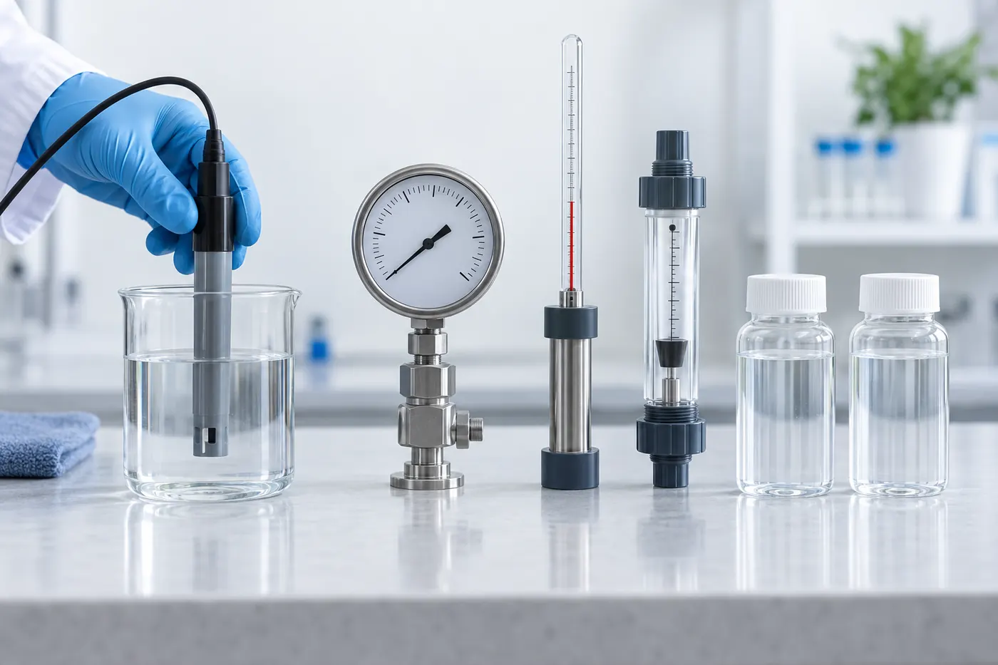
Feed concentration, temperature, pressure, recovery, crossflow, pH and conditioning time can all affect the observed result. A test number is meaningful only when its conditions are recorded and compared with the approved product specification.
Check → Confirm the test recipe, allow the system to stabilize, and record feed and permeate conductivity at the same sampling point in time. Do not compare results obtained under different conditions as though they were equivalent.
2. Conductivity, Flow or Pressure Measurements Are Wrong
A contaminated conductivity probe, an incorrect temperature-compensation setting, a drifting pressure sensor or a sampling mix-up can create an apparent rejection failure. This is especially likely when several normally stable elements change at the same time.
Check → Verify instrument calibration, rinse sampling containers, confirm sample labels and test a known reference element before adjusting production.
3. The Test Housing or Permeate Connection Is Leaking
Damaged O-rings, poorly seated adapters, loose permeate connections or worn fixture seals can allow feed-side water to contaminate the permeate sample. The failed result may follow the test position rather than the element.
Check → Inspect and reseat seals, test the fixture independently where possible, and repeat the test using a known-good element. A dry vacuum or water-immersion integrity test can help distinguish an element leak from a test-stand problem.
4. Adhesive Ratio, Mixing or Cure Is Inadequate
Two-component adhesive must be dispensed at the validated ratio and mixed uniformly. Material used beyond its working time, a partially blocked mixer or unsuitable curing conditions can leave soft, porous or discontinuous sections in the seal.
Check → Review resin and hardener lot numbers, dispense ratio, mixer condition, room conditions, working time and cure record. Inspect retained adhesive samples when available. See the RO membrane epoxy glue requirements when qualifying the bonding process.
5. The Glue Line Is Interrupted or Poorly Positioned
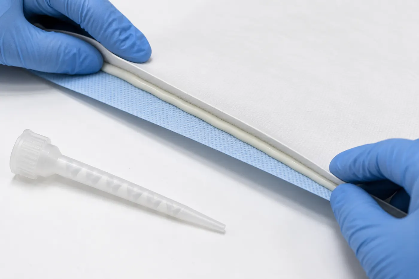
Even correctly mixed adhesive cannot seal a membrane leaf if the bead contains gaps, becomes too narrow, moves away from the intended path or is disturbed during leaf loading. A small discontinuity can become a direct feed-to-permeate leakage path.
Check → Compare the actual glue path with the released work instruction. Inspect bead continuity, width, start and stop points, and the transition near the central tube. If a failed element is opened, document the defect before disturbing the leaf stack.
6. The Active Membrane Surface Is Scratched, Creased or Punctured
Damage can occur during roll handling, slitting, folding, stacking or rolling. Sharp spacer strands, dirty tables, rough guides and trapped particles are common mechanical risks. A defect may be too small to see before assembly but still affect rejection.
Check → Inspect work surfaces and contact parts, review the affected membrane roll and examine the feed spacer for burrs or protruding strands. Compare failures by membrane-sheet and spacer lot.
7. Leaf Preparation or Permeate-Carrier Attachment Is Defective
Incorrect cutting dimensions, folds, wrinkles, contamination or an inadequate carrier-to-tube attachment can create stress and unreliable flow paths inside the leaf. Welding parameters should be validated with the actual carrier, tube and production setup.
Check → Review cut dimensions, weld pattern, handling strength and leaf alignment. Trace the failed element to its permeate carrier lot and preparation record.
8. Rolling Tension or Leaf Alignment Is Unstable
Too little, too much or uneven winding tension can shift the material stack, disturb wet adhesive and create an inconsistent finished geometry. Misaligned leaves may telescope or load the membrane surface unevenly.
Check → Compare tension settings, mandrel condition, finished diameter, straightness and operator observations. For industrial elements, review whether the rolling machine held the released recipe throughout the cycle.
9. Material Storage or Batch Control Has Failed
Membrane sheet, adhesive and converted components can change when exposed to unsuitable temperature, humidity, contamination, sunlight or excessive storage time. A material may also be acceptable on its own but incompatible with the released element recipe.
Check → Confirm shelf life, storage history, packaging condition, lot identity and first-in-first-out control. Quarantine suspect stock rather than mixing it with released materials.
⚠ Important: Do not change several process parameters at once. A quick result is tempting, but simultaneous changes make the actual cause difficult to prove. Change one controlled variable, document it and retest.
A Practical Root-Cause Workflow
- Confirm the failure. Check the formula, samples, instruments and complete test conditions.
- Validate the test stand. Run a stable reference element or move the suspect element to another qualified position.
- Repeat after proper stabilization. Record how rejection and flow change with time.
- Screen element integrity. Use the approved vacuum, pressure-decay or water-immersion method and verify the tester itself is leak-free.
- Look for a pattern. Group failures by date, shift, operator, machine recipe and material lot.
- Review production evidence. Check glue, welding, rolling, curing and dimensional records.
- Open a controlled sample when necessary. A documented teardown of one failed element can be more valuable than repeatedly testing the entire batch.
The sequence should connect with a broader RO membrane element quality-control plan. Final testing is strongest when incoming inspection, process records and material traceability are already in place.
What Should Be Recorded?
- Element serial or batch number and production timestamp
- Membrane sheet, spacer, carrier, tube and adhesive lot numbers
- Cut dimensions, leaf count and released build recipe
- Adhesive ratio, dispense time, mixer and cure conditions
- Rolling-machine recipe, tension record and finished dimensions
- Test pressure, temperature, feed concentration, flow, recovery and stabilization time
- Feed and permeate measurements, integrity result and corrective action
These records turn “low rejection” into a traceable production event. Without them, teams often replace materials or adjust machines based on intuition, while the original cause remains.
Corrective Action by Failure Type
| Confirmed cause | Immediate action | Prevention |
|---|---|---|
| Test-system error | Correct and repeat the test | Calibration schedule and reference-element checks |
| Fixture or seal leak | Replace or reseat the affected seal | Pre-shift fixture inspection and replacement limits |
| Adhesive defect | Hold the affected batch and verify cure | Ratio monitoring, mixer control and retained samples |
| Membrane damage | Quarantine the affected material and elements | Clean handling, smooth contact surfaces and incoming inspection |
| Rolling or alignment defect | Stop, inspect and reset to the released recipe | Recipe control, first-piece approval and trend monitoring |
Frequently Asked Questions
Can low salt rejection always be blamed on the membrane sheet?
No. Test conditions, instrument error, fixture leakage, glue-line defects, leaf damage and assembly variation can all produce a low result. Verify the test system and element integrity before rejecting the membrane-sheet lot.
Why does rejection sometimes improve during the test?
The element and test system may not yet have reached a stable condition. Wetting, flushing and stabilization requirements depend on the membrane and the approved test method. Record the result over time rather than relying on the first reading.
Can a vacuum test measure salt rejection?
No. A vacuum test screens integrity; it does not measure hydraulic membrane performance. Salt rejection and permeate flow require a controlled water test. The two methods answer different questions and work best together.
Should every failed element be cut open?
No. First verify the test system and identify the batch pattern. A controlled teardown is most useful after non-destructive checks have narrowed the likely cause. Record photographs and locations before separating the layers.
What information helps a supplier diagnose the failure?
Provide the element design, material lots, production recipe, glue and cure records, finished dimensions, full test conditions, rejection and flow data, integrity-test result, failure rate and clear photographs. “The rejection is low” alone is not enough for a reliable diagnosis.
Need Help Tracing an RO Element Test Failure?
Send WECOME your element size, material stack, production records and test data. Our team can help review the likely cause and recommend suitable materials, rolling or testing equipment for the next validation step.

Bessie has 10+ years of experience in RO membrane materials and water treatment supply chains. At WECOME, she helps manufacturers and system integrators worldwide source the right membrane components — from feed spacers and permeate carriers to NSF-certified adhesives — backed by hands-on technical support.