


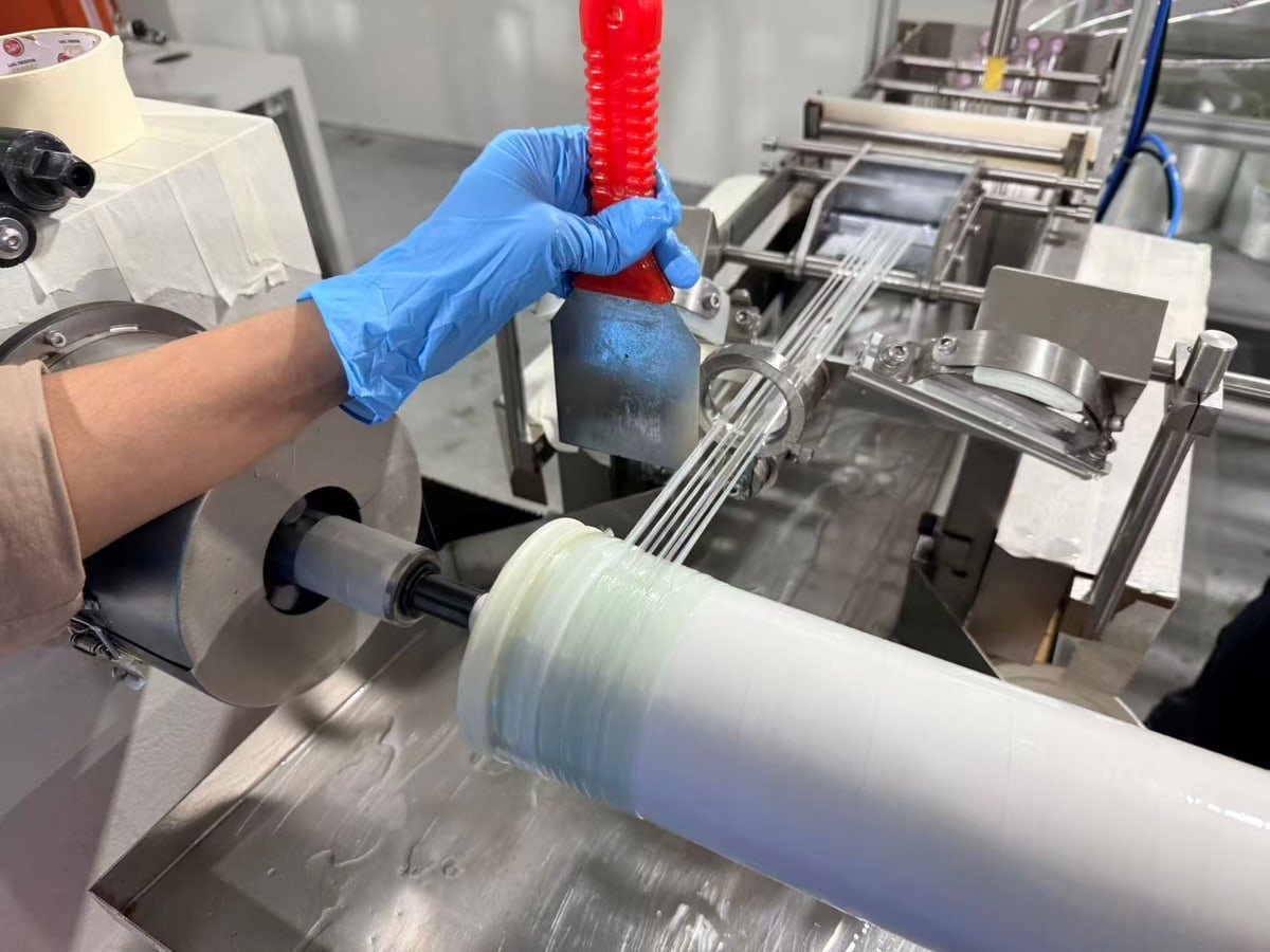
Choosing an RO membrane FRP winding machine means matching a complete exterior-reinforcement process, not simply buying a rotating spindle. The workpiece dimensions, fiberglass wet-out, resin handling, operator cycle and cured outer diameter must work together before the element is released for packaging.
What should you confirm before ordering? Start with the actual element drawing, the approved epoxy and fiberglass, and a representative production trial. WECOME’s engineering feedback gives a workpiece range of 60-200 mm diameter and 50-1100 mm length. For the discussed 4040 and 8040 programs, 3-5 minutes per element includes loading and unloading by one operator. Confirm tooling and the precise dimensional references in the quotation; these figures are not a guarantee for every element construction.
Technical basis: application information supplied by WECOME engineer Zhang, with production media supplied for this article. Resin-specific instructions and project acceptance drawings take precedence over general references below.
Specify RO Element Wrapping, Not Pressure-Vessel Manufacturing
This application winds resin-wetted fiberglass around a spiral-wound RO membrane element to form its exterior reinforcement. It is different from winding the internal membrane leaves, and different again from manufacturing the separate pressure vessel that houses the completed element.
That distinction matters when comparing a fiberglass winding machine for RO membrane elements with general-purpose filament-winding equipment. A search result for tanks, pipes or pressure housings may describe a machine with the wrong fixtures, material path or handling arrangement. Send a drawing and a photograph of the actual element with your enquiry.
The WECOME FRP fiberglass winding machine is the equipment page for this process. This guide focuses on how to compare scope and acceptance requirements rather than repeating a catalogue specification table.
Check Actual Dimensions Before Selecting Fixtures
Engineer Zhang confirmed a diameter range of 60-200 mm and a length range of 50-1100 mm for the discussed equipment. These limits are useful for screening a project, but a format label such as 4040 or 8040 does not replace dimensional verification.
Ask whether each quoted dimension refers to the incoming workpiece, the supported body, the winding length or the finished wrapped element. Tube projections, protected end areas and the way the element is clamped can affect the usable envelope. A number at the upper limit of a range deserves a drawing review rather than an assumption of compatibility.
- Record the body diameter before reinforcement and the required finished maximum diameter.
- Separate overall length, central-tube projection and the length that actually receives fiberglass.
- Define support points and areas that must remain free of resin.
- Confirm the tooling change required between 4040 and 8040 production.
- Supply representative workpieces for the agreed acceptance trial.
A practical buying question is: Can this fixture support our actual element throughout the agreed winding recipe without damaging the ends or obstructing the required reinforcement area? The answer should be tied to the sample and drawing, not just the nominal format.
Use the Complete Operator Cycle to Plan Output
The confirmed 3-5 minute reference for 4040 and 8040 includes loading and unloading by one operator. It should therefore not be described as spindle-running time alone. It also does not establish how every resin batch, cleaning task, changeover or inspection is accounted for across a shift.
At uninterrupted repetition, that cycle corresponds mathematically to 12-20 elements per hour at the winding station. It is not a guaranteed hourly output of cured, accepted and packaged elements. Ask the supplier to time the same sequence you intend to use and list tasks outside the measured cycle.
Now consider the curing area. With an approximately 12-hour room-temperature cure reference for the discussed resin process, same-shift winding capacity is not the same as same-shift packing capacity. Size the curing space, batch identification and release process around actual production hours and the resin supplier’s approved schedule.

Match the Resin Process to the Workstation
Use the specified temperature and mixing instructions
For the resin process described in the engineering feedback, the stated use temperature is below 25 degrees C, with room-temperature curing of approximately 12 hours. Treat both as application references for the selected system, not universal rules for all epoxies. Obtain the resin and hardener technical data sheets, including the approved working-temperature range and cure criteria.
The mixing ratio must follow the adhesive manufacturer’s technical instructions. Do not infer a 1:1 ratio because a product is described as an AB adhesive, and do not interchange weight and volume ratios. Confirm which ratio the dispensing equipment actually controls and how it is checked during acceptance.
Small additions do not mean unlimited pot life
Zhang’s operating feedback calls for adding small quantities to the resin trough repeatedly during production. This is a supply-management approach, not permission to keep an ageing mixed batch indefinitely. The approved pot life, viscosity limits and replacement procedure still apply. Adding fresh mixture does not reset the age of material already in the trough.
Discuss the epoxy adhesive and fiberglass roving together. The equipment proposal should identify the selected materials and trial conditions rather than promising identical results with any resin and fiber combination.
Include cleaning in the technical agreement
The engineering feedback mentions alcohol or ketone-based cleaners such as acetone. The actual cleaner must be approved for the resin, seals, equipment surfaces and waste-handling procedure. Follow the relevant safety data sheets and local requirements for ventilation, ignition control, protective equipment and disposal. Acetone is flammable; see the NIOSH acetone hazard reference. This article is not a cleaning instruction or a solvent-compatibility approval.
Judge Wet-Out, Cured Thickness and Housing Fit Together
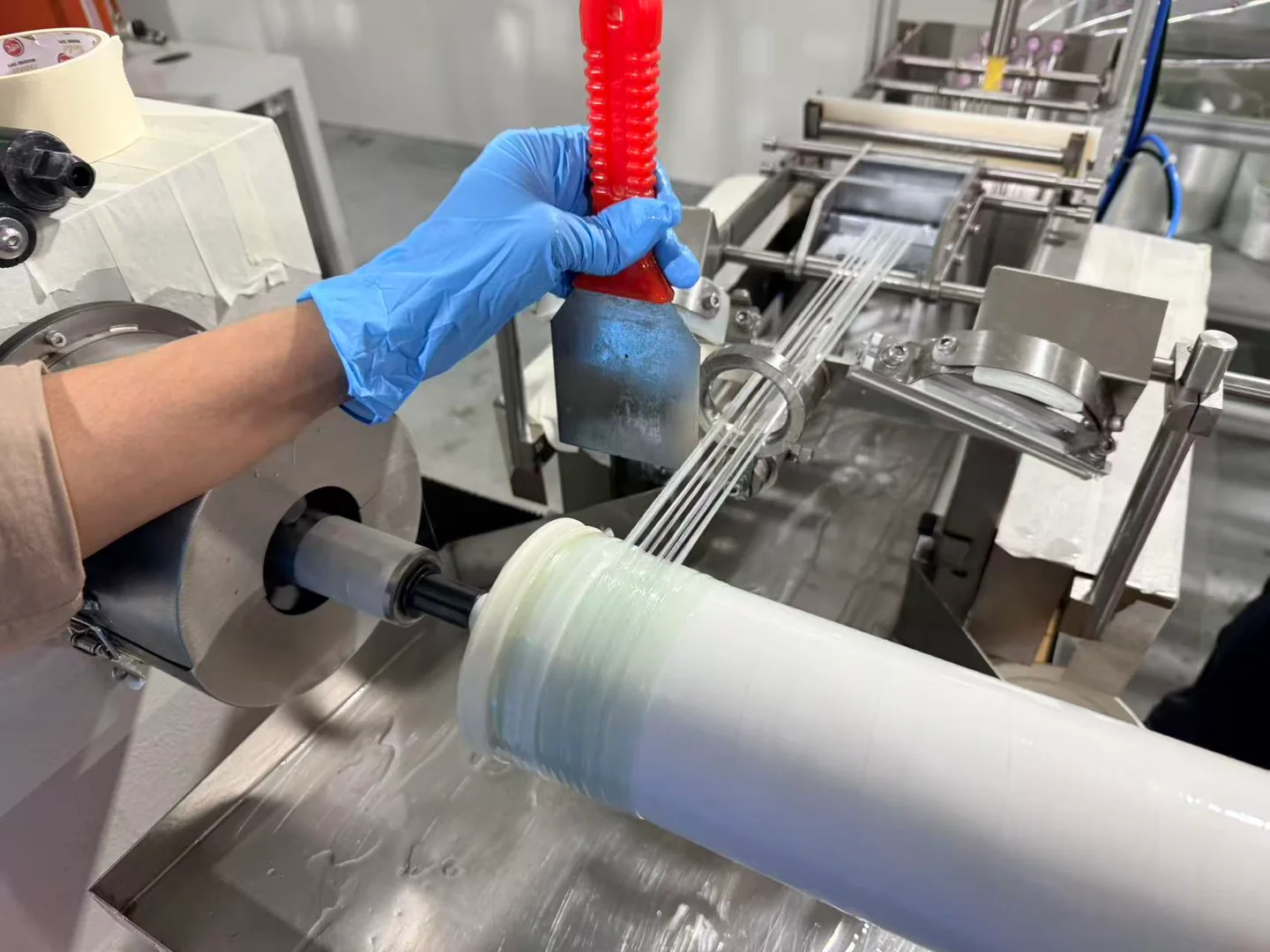
Zhang specifies that the fiberglass strands should be fully immersed in resin at the wetting stage. His process description also includes controlling excess surface resin with a scraper during winding. The equipment supplier and site safety team must define a safe tool arrangement and operator access; the photograph must not be used as an instruction to place hands or loose tools near rotating parts.
Production Clip: Fiberglass Feed and Winding
Ask the acceptance team to inspect for dry fiber, uneven resin distribution and localized buildup. A surface that looks smooth in a photograph does not establish adequate cure, dimensional fit or suitability for the intended service conditions.
The engineering reference for cured fiberglass-shell thickness is 1-3 mm, depending on the element model and working-pressure requirements. It is a design-dependent range, not a universal target or a pressure-rating table. The approved element design and qualification testing determine the required construction.
For example, an assumed 190 mm body with a uniform 2 mm radial wrap would have an estimated diameter of 194 mm. This is a geometry example only, not a recommended 8040 dimension or an installation approval. Use the actual housing specification and element drawing.

Before packaging, the engineering instruction is to remove surface burrs and resin spots. Include surface release in the approved inspection route without removing required structural reinforcement. The RO membrane element quality-control checklist provides a broader context; FRP appearance does not replace integrity or membrane-performance testing.
Compare Two Quotations on the Same Scope
A lower machine price may exclude work that another supplier includes. Use the following questions with both suppliers and request written answers. This is a comparison template, not a ranking of manufacturers or an assertion about any competitor.
| Comparison item | Ask each supplier to state | Evidence to request |
|---|---|---|
| Workpiece and fixtures | Actual diameter, length references, support points and changeover scope. | Marked drawing and representative trial workpieces. |
| Resin and fiberglass | Approved material identities, ratio basis, wetting arrangement and included dosing equipment. | TDS/SDS and a material-matched trial. |
| Operator cycle | Operators required, cycle start/end and tasks excluded from the stated output. | Timed run with the agreed workpiece and recipe. |
| Curing provision | Whether racks, transfer arrangements and cure tracking are included or buyer-supplied. | Layout and agreed release procedure. |
| Finished quality | Thickness target, maximum outer diameter, surface criteria and inspection method. | Sample inspection record against the approved drawing. |
| Safety and support | Guarding, safe process-tool access, cleaning, training and consumables. | Risk assessment, manuals and itemized delivery scope. |
Do not compare quotations using an old winding-system model code alone. The supplied configuration and acceptance results matter more than a familiar nameplate. Require the final bill of materials and the signed technical scope to agree before placing the order.
Prepare a Factory Acceptance Test Before Shipment
A useful factory acceptance test, or FAT, checks the process you are purchasing. Agree on sample quantities, drawings, material batches, measurement methods and pass/fail criteria before the trial. Do not invent a tolerance during the final inspection because a quotation omitted it.
- Verify fit: demonstrate loading, support and removal of the agreed element constructions, including the protected end areas.
- Verify materials: identify resin, hardener and fiberglass, then check the specified ratio and resin condition using the agreed method.
- Observe winding: inspect wet-out and distribution under the approved safeguarded operating arrangement.
- Time the complete cycle: record operator count and the same loading-to-unloading sequence used in the output agreement.
- Inspect after cure: measure the agreed locations for shell thickness and maximum outer diameter, and check surface acceptance. Allow the specified cure time rather than inspecting only freshly wound samples.
- Document release: record results, deviations and corrective actions, together with the delivered configuration and training scope.
Include guarding and safe access in the trial scope. OSHA’s overview of hazardous machine motions explains the hazards associated with rotation and moving interfaces. Use it as background, not as proof that a photographed workstation or supplied machine meets a particular jurisdiction’s requirements.
Frequently Asked Questions
Does the 3-5 minute cycle include handling?
Yes. Zhang confirmed that the discussed 4040 and 8040 reference includes loading and unloading by one operator. Confirm the specific recipe and any remaining non-cycle tasks before estimating shift output.
Is a 12-hour cure suitable for every epoxy?
No. Approximately 12 hours at room temperature is the reference supplied for the discussed process. The selected resin manufacturer’s temperature, cure and release requirements must be checked; elapsed time alone is not a universal acceptance test.
Can the same shell thickness be used for every element?
No. The stated 1-3 mm range depends on model and service requirements. Confirm the approved thickness and finished outer diameter for each construction; extra thickness is not automatically compatible with the housing.
Does FRP wrapping prove an element’s operating pressure?
No. The outer reinforcement is one part of the element design. A winding machine specification or visual surface check does not establish pressure capability, salt rejection or service life.
Request a Configuration Around Your Actual Element
Send WECOME your element drawing, bare and finished diameters, winding length, fiberglass specification, epoxy TDS/SDS, target output and acceptance requirements. Include the housing-fit limits and any tooling changes required between products.
For a wider factory project, identify the FRP station’s interfaces with your RO membrane production line, especially material supply, curing space and inspection.
Discuss Your FRP Winding RequirementsTechnical Basis and Scope
WECOME engineer Zhang supplied the application dimensions, operator-cycle definition, resin-handling references and cured-shell inspection points used here. The production photograph was supplied with those materials. These references describe the discussed application, not every available configuration. Numeric examples are explicitly illustrative; final specifications belong in the agreed technical documentation.

Bessie has 10+ years of experience in RO membrane materials and water treatment supply chains. At WECOME, she helps manufacturers and system integrators worldwide source the right membrane components — from feed spacers and permeate carriers to NSF-certified adhesives — backed by hands-on technical support.