

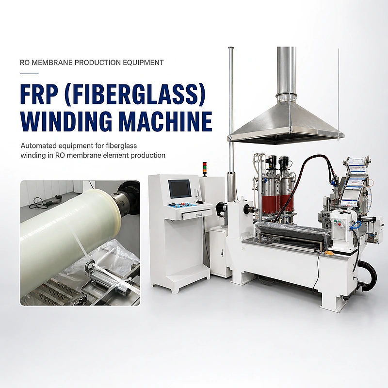
The FRP (Fiberglass) Winding Machine meters and mixes two-component epoxy, wets fiberglass roving and winds a programmed reinforcement layer around industrial spiral-wound membrane elements.
Built primarily for 4040 and 8040 RO membrane elements, the IN-FRP-02A combines an automatic glue mixing/dipping system with a computer-controlled horizontal winding station. The traversing fiberglass path moves from the center toward each end and returns according to the approved winding program before the reinforced element is transferred to vertical curing.
Automatic FRP Winding for 4040 and 8040 RO Membrane Elements
The machine applies resin-wetted fiberglass wrap around the prepared industrial membrane element to form a controlled exterior reinforcement layer. The approved two-component epoxy system is metered, statically mixed and delivered to the dipping section before the roving follows the programmed winding path.
Consistent wet-out, winding angle, traverse position and tension help reduce dry fiber, resin-rich areas and uneven buildup. Final external diameter, wall thickness, cure and mechanical suitability still depend on the customer’s element design, fiberglass specification, resin chemistry and acceptance testing.
From Two-Component Epoxy to a Cured FRP Outer Layer
Meter Resin A + B
Measure the approved epoxy and hardener at the validated weight ratio.
Static Mixing
Combine both components sufficiently before the material reaches the dipping path.
Wet Fiberglass
Guide roving through the mixed epoxy while controlling wet-out and excess resin.
Programmed Winding
Traverse center-to-edge and return passes around the rotating membrane element.
Vertical Cure
Transfer the wrapped element to the approved orientation and cure schedule.
Key Production Advantages
Automatic two-component metering
The KS05-50 dispensing system supports a stable mix ratio, controlled shot volume and static mixing for the approved epoxy.
Computer-controlled winding path
Operators enter validated process parameters and the motion system coordinates spindle rotation with horizontal traverse.
Controlled fiberglass wet-out
The dipping path helps distribute mixed resin through the roving before it reaches the rotating element.
Adjustable winding pattern
Winding angle, traverse, tension and pass sequence can be configured around the approved 4040 or 8040 reinforcement design.
Process pause and restart
The winding program can be started or stopped during operation when the validated production process requires intervention.
Lower manual variability
Automated metering and programmed winding reduce dependence on hand mixing, hand wet-out and visually estimated wrap paths.
FRP Fiberglass Winding Machine Specifications
| Technical Item | Standard Reference |
|---|---|
| Product Name | FRP (Fiberglass) Winding Machine for Industrial RO Membrane Elements |
| Model Number | IN-FRP-02A |
| Primary Application | Automatic epoxy/fiberglass exterior winding for industrial 4040 and 8040 RO membrane elements |
| Additional Cycle Reference | 4021: approximately 2 minutes per element; tooling compatibility must be confirmed because the supplied primary application range lists 4040 and 8040 |
| Production Reference | 4040/8040: approximately 3-5 minutes per element |
| Glue Mixing and Dipping System | KS05-50 automatic two-component system |
| Horizontal Winding System | Supplied as FW200×100; the official legacy product record lists FW200×1000. Confirm current nameplate and final BOM. |
| Control Method | Siemens small PLC and touchscreen for machine/auxiliary control; computer and motion-control architecture for the winding program according to approved configuration |
| Electrical Supply | AC 380 V; main winding machine 5 kW plus glue dispenser 4 kW |
| Air Supply | 0.6-0.7 MPa clean, dry compressed air |
| Winding Main Device | 2588 × 1195 × 1155 mm (L × W × H) |
| Electrical Cabinet | 696 × 460 × 1570 mm (L × W × H) |
| Automatic Dispenser | 1420 × 1150 × 2038 mm (L × W × H) |
| Fiberglass Frame | 970 × 1861 × 1300 mm (L × W × H) |
| Equipment Weight | Approximately 1660 kg |
| Packing Reference | Three listed package envelopes: 2790 × 1330 × 1700 mm; 1450 × 1070 × 2130 mm; and 1000 × 900 × 1310 mm |
The 5 kW and 4 kW values are connected-load references. Confirm phase/frequency, peak demand, package allocation for the four modules, gross weights, control architecture and exact winding-system model in the signed technical agreement.
Epoxy Mixing and Delivery Parameters
| Dispensing Item | Reference Configuration |
|---|---|
| Mixing Requirement | Stable proportion, accurate measurement and sufficient mixing |
| Mix Ratio | 100:100 by weight as the supplied standard reference; customizable for an approved resin system |
| Delivery per Shot | 38-196 ml/shot |
| Maximum Delivery Reference | 1500 ml/min |
| Delivery Accuracy | Specified reference ±2% |
| Mixing Method | Static mixing |
| Legacy Tank Reference | Separate 60 L SUS304 resin and hardener pressure tanks with vacuum-suction feeding and low-level sensing; verify current project configuration |
| Static Mixer Reference | Legacy product information lists a double-liquid valve with Switzerland MIXPAC MS13-32; final mixer depends on resin chemistry and flow requirements |
Winding-System Motion References
| Motion Item | Legacy Reference Requiring Project Confirmation |
|---|---|
| Maximum Spindle Speed | 200 rpm |
| Maximum Core/Product Diameter | 200 mm |
| Maximum Product Weight | 20 kg including the clamped product |
| Winding Length | ≤1000 mm; horizontal trolley travel ≤1200 mm |
| Maximum Trolley Speed | 0.5 m/s |
| Winding Angle | 54°-90° |
| Trolley Repeat Positioning | ±0.25 mm |
| Winding Tension | ≤30 kg reference |
| Fiberglass Capacity | Up to six roving packages in the legacy configuration |
These motion values come from the official legacy FW200×1000 record and are not automatically guaranteed for the current IN-FRP-02A project. Reconfirm the actual membrane-element mass, length, diameter, winding pattern and hardware before quotation.
Winding-Cycle and Output Planning
Approximately 12-20 elements/hour
This is the theoretical winding-cycle range before loading, resin preparation, manual excess-resin control, inspection, cleaning, changeover and planned downtime.
Compatibility must be verified
The cycle reference is supplied, but the standard application statement names 4040 and 8040. Confirm the 4021 fixture, winding length, resin quantity and program during FAT.
Each wrapped element must be transferred safely to the specified vertical curing position. Racks, batch identity, resin pot life, cure time and downstream packaging capacity should be sized so the winding station does not create uncontrolled work-in-process.
Resin Handling, Recovery and Safe Operation
Controlled process conditions
- Use only the approved resin/hardener ratio and static mixer
- Track resin temperature, viscosity, pot life and batch identity
- Control roving wet-out without dry fiber or heavy resin pooling
- Use ventilation, PPE and spill controls required by the material SDS
Do not automatically reuse collected resin
- Mixed epoxy continues reacting after resin and hardener combine
- Reuse depends on remaining pot life, contamination and validated work instructions
- Material outside the approved condition must follow the plant’s waste procedure
- Never return mixed material to unmixed resin or hardener tanks
What FRP Winding Improves – and What It Does Not Prove
Controlled reinforcement variables
- Resin/hardener proportion and shot volume
- Fiberglass wet-out, winding path, angle and tension
- Layer distribution along the element body
- Repeatable exterior reinforcement recipes
Requires separate validation
- Finished pressure rating and burst resistance
- Vacuum integrity, water flux and salt rejection
- Resin cure, bond quality and long-term chemical compatibility
- Final diameter, wall thickness and surface acceptance
Where This FRP Winding System Fits Best
4040 and 8040 RO factories
Routine industrial element exterior reinforcement using validated fiberglass and epoxy recipes.
OEM and ODM production
Stored winding programs for customer-specific layer counts, angles, resin quantities and finished diameters.
Manual winding upgrades
Manufacturers replacing hand mixing and visual winding paths with metered adhesive and coordinated motion control.
New-element validation
Production-representative trials for new fiberglass, resin, winding patterns, reinforcement thickness or cure schedules.
4021 project programs
Possible according to the supplied cycle reference, subject to fixture and winding-system confirmation.
Turnkey industrial lines
Exterior-reinforcement station coordinated with rolling, curing, trimming, integrity testing and final assembly.
FRP Quality Checks Before Final Packaging
During mixing and winding
- Correct resin/hardener identity, ratio and delivery quantity
- Continuous fiberglass feed and consistent wet-out
- Approved winding angle, pass count, tension and traverse
- No dry fiber, excessive resin pooling, air pockets or skipped areas
After winding and cure
- Finished diameter, reinforcement length and wall buildup
- Surface continuity without sharp fibers or heavy ridges
- Cure condition, hardness and tack-free status
- Batch record and release to approved inspection or packaging
Connect resin and winding records to the plant’s RO membrane element quality control checklist. Use the glue-consumption calculator only after the FRP recipe and counting basis are defined.
Configuration, FAT and Delivery
| Project Input | What WECOME Needs to Confirm |
|---|---|
| Element Drawing | 4040, 8040 or requested 4021 format; body diameter, winding length, element mass, clamping points and protected end areas |
| Fiberglass Specification | Roving type, tex/yield, package size, number of ends, surface treatment, required tension and storage condition |
| Epoxy System | Resin/hardener TDS and SDS, weight ratio, viscosity, density, pot life, cure schedule, required shot volume and cleaning method |
| Winding Recipe | Angle, pass sequence, traverse limits, spindle speed, trolley speed, tension, reinforcement length, finished thickness and diameter |
| Control Architecture | Siemens PLC/touchscreen functions, industrial computer, motion card, winding software, data/recipe needs and final BOM |
| Utilities and Safety | 380 V supply, compressed-air capacity, ventilation, guarding, operator access, resin containment and curing-rack layout |
| FAT Method | Customer material trial, mix-ratio verification, delivery accuracy, cycle time, winding pattern, wet-out, finished dimensions, alarms and safety checks |
| Packing and Training | Approved module layout, packing allocation, gross weights, manuals, SDS controls, maintenance plan and operator training |
Frequently Asked Questions
What does an RO membrane FRP winding machine do?
It meters and mixes two-component epoxy, wets fiberglass roving and winds a programmed exterior reinforcement layer around an industrial spiral-wound membrane element before controlled curing.
Which membrane element sizes can the machine support?
The supplied primary range covers 4040 and 8040 RO membrane elements. A 4021 cycle reference is also supplied, but the fixture, winding length, element mass and program must be confirmed before quotation.
What are the reference winding cycle times?
The supplied references are approximately three to five minutes for a 4040 or 8040 element and approximately two minutes for a 4021 element. Shift output must include loading, resin preparation, inspection, cleaning, curing transfer and planned downtime.
Can the epoxy mixing ratio be customized?
Yes. The supplied standard reference is 100:100 by weight, while the metering system can be configured for an approved resin system. The final ratio, pump sizing, mixer and delivery accuracy require the adhesive technical data and sample trials.
What is the difference between the Siemens PLC and computer control system?
They can serve different layers of the machine. The PLC and touchscreen may manage auxiliary equipment, interlocks and operation, while the industrial computer and motion-control card execute the winding path. The final architecture must be listed in the BOM.
Can excess mixed epoxy be returned to the dipping tank?
Only when the approved process permits it and the material remains within pot life, cleanliness and viscosity limits. Mixed epoxy must never be returned to unmixed component tanks, and unsuitable material must follow the plant’s disposal procedure.
Does an FRP wrap automatically prove the element pressure rating?
No. Winding controls reinforcement placement, but pressure suitability depends on the complete design, material properties, cure quality, finished dimensions and qualification testing.
What information is required for an accurate quotation?
Provide the element drawing, fiberglass specification, epoxy TDS/SDS, mix ratio, pot life, cure schedule, winding pattern, target thickness and diameter, required output, plant utilities, safety requirements and FAT criteria.
Related Equipment and Technical Resources
Confirm the Fiberglass, Epoxy and Winding Recipe
Send the element drawing, roving specification, epoxy TDS/SDS, mix ratio, cure schedule, target reinforcement and workshop layout for a project-specific FRP winding proposal.