

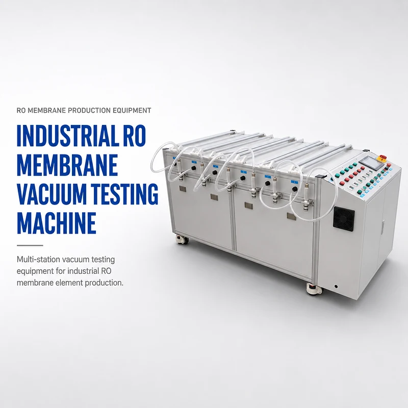

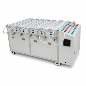
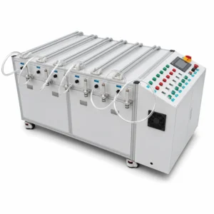
The Industrial RO Membrane Vacuum Testing Machine applies a programmed negative-pressure test to screen the overall air-tightness of 4040, 8040, 4021 and 2540 spiral-wound membrane elements.
The FSQ-01 combines two detection groups, a Feiyue vacuum pump, 10 L negative-pressure storage, a 0-100 kPa gauge and Siemens PLC/touchscreen control. Pumping, holding and measurement times can be set for the approved product recipe, while test results support production quality control and traceability.
Vacuum Air-Tightness Testing for 4040 and 8040 RO Elements
This industrial RO membrane vacuum testing machine evaluates whether a finished element maintains the approved negative-pressure condition over a programmed test interval. The system evacuates the connected element/fixture, stabilizes the circuit, monitors the pressure response and compares the result with the validated acceptance threshold.
The method provides dry, non-destructive integrity screening without immersing the element in water. It can be positioned after curing and industrial end trimming, with the exact sequence relative to FRP reinforcement and final assembly defined by the plant’s approved quality plan. See the RO membrane vacuum leak testing guide.
Industrial Vacuum Test Circuit and Decision Flow
Element Fixture
Seal the approved 4040, 8040, 4021 or 2540 element with format-specific adapters.
10 L Reservoir
Negative-pressure storage supports a more stable test circuit and repeatable evacuation.
Pressure Gauge
Monitor the configured negative-pressure condition within the 0-100 kPa reference range.
Feiyue Pump
Generate the required vacuum during the programmed pumping stage.
PLC Decision
Hold, measure, compare and display green pass or red reject/alarm according to the recipe.
Key Quality-Control Advantages
Dry non-destructive screening
Vacuum testing evaluates overall air-tightness without filling the membrane element with process water.
Two-group detection architecture
Two detection groups support flexible fixture or test-channel planning; actual simultaneous throughput must be defined in the FAT method.
Recipe-based timing
Pumping, holding and testing times are entered on the HMI for the validated format and acceptance method.
Automatic pass/reject indication
Green and red indicators communicate the programmed decision, with alarm handling for rejected or abnormal tests.
Production data support
Recorded results can support batch traceability, quality review, rework decisions and process-improvement analysis.
One-operator QC station
One operator manages fixture loading, recipe selection, seal checks, result review and safe unloading.
Industrial RO Membrane Vacuum Testing Machine Specifications
| Technical Item | Standard Reference |
|---|---|
| Product Name | Industrial RO Membrane Vacuum Testing Machine |
| Model Number | FSQ-01 |
| Primary Function | Dry negative-pressure air-tightness screening of industrial spiral-wound membrane elements |
| Compatible Element Programs | Industrial 4040, 8040, 4021 and 2540 membrane elements with approved fixtures/adapters |
| Detection Method | Two-group vacuum detection; define whether groups run independently, alternately or simultaneously in the approved configuration |
| Operation | One operator |
| Production Reference | Approximately 30-40 seconds per element |
| Vacuum Pump | Feiyue |
| Negative-Pressure Gauge | Ottonix, 0-100 kPa reference range |
| Negative-Pressure Storage | 10 L tank |
| Control Method | Siemens small PLC and touchscreen HMI |
| Recipe Parameters | Pumping time, holding time and testing time set on touchscreen; detection/holding pressure configured for the approved test method |
| Result Indication | Green pass; red reject with alarm according to the programmed acceptance rule |
| Electrical Supply | AC 220 V / 1.5 kW |
| Machine Dimensions | 1200 × 750 × 1100 mm (L × W × H) |
| Equipment Weight | Approximately 180 kg |
| Packing Dimensions | 1310 × 840 × 1200 mm |
The current 1.5 kW value supersedes the 1 kW reference on the legacy product page. Final pump model, gauge brand/model, fixture count, data-storage/export functions, pressure convention and acceptance logic must be listed in the signed technical agreement.
Test-Cycle and Capacity Planning
Up to 120 elements/hour theoretically
This mathematical reference excludes fixture loading, adapter inspection, recipe changeover, result review, rejected-part handling and planned downtime.
Up to 90 elements/hour theoretically
Actual shift output depends on element size, evacuation volume, target vacuum, stabilization time, test duration and operator handling.
“Two group detection” describes the supplied detection architecture. Confirm whether the groups operate simultaneously, alternately or as independent fixtures before using them in an hourly-capacity calculation.
How a Vacuum Decay Recipe Should Be Defined
| Recipe Variable | Why It Matters |
|---|---|
| Element and Fixture | Adapter geometry, seals, tube connection and internal test volume must match the 4040, 8040, 4021 or 2540 product |
| Target Negative Pressure | Must be high enough to reveal unacceptable leakage without exceeding the approved dry-test condition |
| Pumping Time | Determines whether the circuit reaches the required starting vacuum consistently |
| Stabilization / Holding Time | Allows transient pressure and temperature effects to settle before the measurement window |
| Measurement Time | Defines how long the pressure response is observed |
| Allowable Pressure Change | Pass/reject threshold established from approved samples, process capability and the customer’s quality standard |
| Retest Rule | Defines how to distinguish an element defect from a dirty adapter, damaged seal, loose hose or operator-loading issue |
| Record Format | Product ID, batch, recipe, result, measured response, operator/time and disposition required for traceability |
Pass, Reject and Retest Decisions
Release as a passing screen
- Correct recipe and fixture were used
- Target vacuum and stabilization conditions were reached
- Pressure response remained within the validated limit
- Test record and product identity are complete
Reject or hold for investigation
- Pressure change exceeded the approved threshold
- Target vacuum could not be reached or held
- Adapter seal, hose or fixture condition is uncertain
- Product identity, recipe or test record is incomplete
What Vacuum Testing Can Detect – and What It Cannot Prove
Appropriate screening purpose
- Overall air-tightness against a validated decay threshold
- Potential glue-line, seal or assembly leakage requiring investigation
- Batch-to-batch integrity screening under repeatable dry conditions
- Data support for hold, rework and release decisions
Separate tests and investigations
- It does not automatically locate the exact leak point
- It does not measure permeate flow or salt rejection
- It does not prove burst pressure or long-term mechanical strength
- It cannot distinguish a product leak from a bad fixture without retest controls
Where This Industrial Vacuum Tester Fits Best
4040 and 8040 factories
Routine dry integrity screening of industrial elements under a validated vacuum-decay recipe.
4021 and 2540 programs
Additional formats using approved adapters, test volumes and acceptance limits.
Post-cure production QC
Screening after adhesive cure and dimensional finishing according to the plant’s process route.
OEM and ODM traceability
Recipe-controlled records for different customer formats, batches and quality thresholds.
Rework verification
Controlled retesting after an approved corrective action, with fixture integrity checked first.
New-element validation
Establishing suitable test conditions and acceptance windows using known-good and seeded-leak samples.
Daily Quality Checks for Reliable Vacuum Results
Machine and fixture checks
- Clean adapters, seals, hoses and connection surfaces
- Vacuum pump condition and 10 L reservoir integrity
- Gauge zero/reference check and recipe access control
- Leak check using a known-good blank or reference part
Product and record checks
- Correct product identity, format and test adapter
- Element temperature and cure condition within the approved range
- Result, alarm and retest disposition recorded
- Failed parts physically controlled to prevent accidental release
Include these controls in the RO membrane element quality control checklist. Calibration interval and reference standards should follow the customer’s quality system.
Configuration, FAT and Delivery
| Project Input | What WECOME Needs to Confirm |
|---|---|
| Element Formats | 4040, 8040, 4021, 2540 or project-specific end geometry, center-tube connection and test volume |
| Detection Groups | Number of fixtures, independent/simultaneous/alternating logic, valve arrangement and result display for each group |
| Test Recipe | Target vacuum, pumping time, stabilization time, measurement time, allowable change, retest rule and pass/reject indication |
| Reference Samples | Known-good elements, known-leak or calibrated reference parts and the method used to establish the acceptance threshold |
| Data Requirements | Product ID, batch/operator fields, result storage, export format, user permissions and integration requirements |
| Utilities and Environment | 220 V supply, ambient temperature range, ventilation, noise expectations, installation surface and service clearance |
| FAT Method | Fixture leak test, pump-down repeatability, known-good/known-leak trials, cycle demonstration, alarms, retest logic and data review |
| Documentation and Packing | Approved technical specification, fixture drawings, BOM, manual, test-recipe guidance, calibration/maintenance plan and export packing |
Frequently Asked Questions
What does an industrial RO membrane vacuum testing machine do?
It applies a programmed negative-pressure test and monitors the pressure response to screen the overall air-tightness of an industrial spiral-wound membrane element against a validated acceptance threshold.
Which industrial RO membrane formats can the FSQ-01 test?
The supplied range covers 4040, 8040, 4021 and 2540 elements. Each format requires approved adapters, test volume, timing and acceptance limits.
What does “two group detection” mean?
It describes the supplied two-group detection architecture. Whether both groups operate simultaneously, alternately or independently must be confirmed in the valve/fixture design and FAT method before calculating capacity.
How is a pass or reject decision made?
The machine reaches the programmed negative-pressure condition, holds and measures the response, then compares it with the validated acceptance rule. Green indicates pass; red indicates reject/alarm according to the configured logic.
What is the expected testing cycle?
The supplied reference is approximately 30-40 seconds per element. Actual time depends on element size, circuit volume, target vacuum, pumping time, stabilization, measurement duration and operator handling.
Can the machine identify the exact leak location?
No. It screens overall air-tightness. A failed result indicates that the product or test circuit exceeded the acceptance limit; separate investigation is needed to locate the defect and exclude fixture leakage.
Does vacuum testing replace flow and salt-rejection testing?
No. Vacuum testing evaluates dry air-tightness. Hydraulic performance tests are still required when the quality plan calls for permeate flow, salt rejection, pressure or recovery verification.
What information is required for an accurate quotation?
Provide element drawings and formats, fixture connections, target vacuum, timing, pressure-change threshold, retest rule, known-good and known-leak samples, data/export needs, required throughput and FAT criteria.
Related Equipment and Technical Resources
Confirm the Element, Fixture and Acceptance Recipe
Send element drawings, adapter details, target vacuum, timing, acceptance threshold, reference samples, data requirements and required output for an FSQ-01 proposal.