
Compare what each method reveals, where false results begin, and how to build a faster integrity-screening and fault-localization workflow.
 Dry integrity screening
Dry vacuum testing is usually the better production-line method for repeatable, recordable RO membrane element integrity screening, while water immersion bubble testing is usually more useful for locating a visible leak after a product has already failed or during process validation. Neither method proves salt rejection or water flux, and neither should use a universal pressure, time or pass limit without validation on the actual element, fixture and test volume.
What Each Leak Test Actually Checks
The methods are often discussed as substitutes, but they produce different evidence. The correct choice depends first on whether the QC question is “Does the connected test circuit remain tight?” or “Where is gas escaping?”
Measures the response of a sealed circuit
The element is connected to a controlled vacuum circuit. After evacuation and stabilization, the system monitors pressure change over a defined hold or measurement interval. A result outside the validated limit indicates that the complete connected circuit is not behaving like an accepted reference.
Uses visible gas release to locate a leak
The approved test circuit is pressurized with gas and the required area is immersed. A continuing bubble stream can reveal a leak region. The method is visual and useful for localization, but the absence of visible bubbles does not automatically prove that every small defect is absent.
For production teams, this distinction matters. A pressure-change result can be logged, compared across shifts and linked to a serial or batch record. A bubble test gives location evidence that can help diagnose an end seal, adapter, shell, tube or assembly problem. Treating both as a single “leak test” hides the most important difference in their outputs.
Dry vacuum sequence
A typical screen separates evacuation, stabilization and measurement instead of judging the initial pump-down alone.
- 01Load the correct element and adapters, then verify seals and recipe.
- 02Evacuate the defined circuit to the validated test condition.
- 03Allow pressure and temperature effects to stabilize.
- 04Measure pressure rise or decay across the controlled interval.
- 05Compare with the approved limit and store the result.
Water immersion sequence
A typical localization test controls pressure, wetting, observation and operator interpretation.
- 01Connect the approved air circuit and confirm a safe pressure limit.
- 02Immerse the defined area and remove trapped surface air.
- 03Apply the validated internal differential pressure.
- 04Observe for a continuing bubble stream for the defined time.
- 05Mark the leak region, release pressure and document disposition.
How Dry Vacuum Integrity Testing Works in Production
A dry vacuum test is attractive when the factory needs a short, repeatable screening cycle without wetting the membrane element.
The machine draws the connected element and fixture toward a defined negative-pressure condition. The controller then evaluates whether the pressure response remains within an approved window. The result is affected by the element, but also by every hose, fitting, valve, seal and adapter included in the test volume. A failed result therefore means “the test circuit did not meet the validated limit,” not automatically “the membrane sheet is defective.”
Dry operation removes the soaking, draining and post-test drying steps associated with immersion. It also avoids adding test water to a semi-finished element and makes PLC-based cycle control, alarms and records easier to standardize. See the full RO membrane vacuum leak testing guide for fixture checks and method-development details.

How Water Immersion Bubble Testing Helps Locate a Leak
Water immersion is valuable when engineers need visual evidence of where gas is leaving the element or connected component.
The element is connected to an approved gas source and subjected to a controlled positive differential pressure while the relevant area is submerged. A repeatable stream of bubbles can help identify the leak region. This is especially useful during new-process validation, root-cause investigation, rework confirmation or evaluation of an unusual dry-test failure.
The wet method also adds handling. The tank water must be controlled, the element must be drained and dried as required, and the team must prevent mix-ups between wet-tested and dry inventory. Water quality, tank cleanliness and storage after testing become part of the process. If the test occurs before final packaging, the drying requirement should be included in production capacity and contamination-risk calculations.
- Approved safe internal pressure and pressure regulator
- Defined immersion area, depth and observation time
- Method for removing harmless trapped surface air
- Rule for continuous, intermittent and isolated bubbles
- Water quality, replacement frequency and tank cleaning
- Post-test draining, drying, segregation and identification
Dry Vacuum vs. Water Immersion: Practical QC Trade-Offs
The table describes common operating characteristics, not a universal performance ranking. Detection capability depends on the validated equipment, fixture, product and work instruction.
| Decision factor | Dry vacuum decay | Water immersion bubble test |
|---|---|---|
| Primary evidence | Pressure response of the entire connected test circuit. | Visual bubble emission from a leak region. |
| Best typical role | Repeatable 100% or high-frequency production screening. | Fault localization, validation, investigation and selected rechecks. |
| Leak location | Usually does not identify the exact leak point by itself. | Can reveal a visible source region when the leak produces observable bubbles. |
| Data and traceability | Well suited to PLC recipes, pass/fail records and trend analysis. | Often operator-observed; photos or video and a location code improve records. |
| Handling state | Element remains dry. | Element becomes wet and may require controlled drying and segregation. |
| Operator influence | Reduced by automated timing and limits, but loading and seal condition still matter. | Observation, lighting, trapped air and bubble interpretation can affect the result. |
| Typical cycle burden | Load, evacuate, stabilize, measure and unload. | Connect, pressurize, immerse, stabilize, observe, drain, dry and manage water. |
| False-result risks | Fixture leak, damaged seal, temperature change, unstable pressure and wrong recipe. | Trapped air, insufficient wetting, low contrast, missed small bubbles and uncontrolled pressure. |
| Automation potential | High for timing, evaluation, alarm and record capture. | Lower unless vision and tightly controlled test hardware are added. |
| What it cannot prove | Neither method confirms salt rejection, permeate flow, pressure-drop behavior or long-term hydraulic performance. | |
Detection Limits Depend on the Complete Test System
A leak method is only as credible as its demonstrated ability to separate accepted products from relevant defects under normal production variation.
For dry testing, pressure response can change when the connected volume changes, a hose expands, an adapter is not fully seated, an O-ring is damaged, the element temperature differs from the fixture or the stabilization period is too short. Pump capacity determines how quickly the target condition is reached, but pump size alone does not define detection capability.
For immersion testing, bubble visibility changes with leak path, applied differential pressure, surface wetting, water clarity, lighting, viewing angle and observation time. A single bubble released from a surface recess is not the same as a continuing stream from a leak. The work instruction should define that difference.
Test the test system
Run a blank or verified tight reference to detect hose, valve, adapter and seal deterioration before rejecting production.
Challenge the method
Use known-good and controlled known-defect samples that represent the smallest defect the process intends to screen.
Prove repeatability
Repeat across operators, shifts, element formats and expected temperature conditions before setting final limits.
Maintain measurement confidence
Define calibration or verification intervals for pressure instruments, timers and any reference leak device used.
Prevent result shopping
State when one controlled retest is allowed, what must be checked first and which result determines disposition.
Use more than pass/fail
Monitor values by product, line, shift and fixture head to identify drift before rejects or escapes increase.
General standards explain principles, not an RO element acceptance limit
ASTM E515 describes bubble emission as a leak-location, go/no-go technique and notes the role of operator skill. ASTM E2930 explains how pressure-change tests depend on equipment, duration, temperature, accuracy and the selected pressure differential. These documents support method-development thinking, but they are not product-specific acceptance standards for spiral-wound RO membrane elements. Your released specification must be validated against your own product and risk.
Compare Total Handling Time, Not Only the Test Timer
A method that observes for 20 seconds can still consume several minutes of floor time after connection, immersion, draining and drying are included.
Connection
Adapter choice, element identification and loading ergonomics affect both methods.
Controlled cycle
Include evacuation or pressurization, stabilization, measurement and result evaluation.
Post-test handling
Dry vacuum usually proceeds directly to unload; immersion adds draining and potentially drying.
Release evidence
Capture recipe, result, fixture head, operator, date, product and disposition.
Capacity should be calculated from actual shift conditions: product mix, fixture count, changeover, start-up verification, retests, maintenance, breaks and expected availability. A four-head household station does not automatically produce four times the throughput if loading is sequential or if one operator performs upstream and downstream tasks. Likewise, two test groups on an industrial machine do not prove simultaneous capacity until the control logic and cycle have been confirmed.
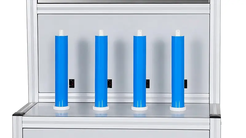
For reference, WECOME’s household dry vacuum configuration is designed around compact 1810 to 3013 formats with four fixture positions and adjustable test time and pressure. The industrial configuration is intended for formats such as 2540, 4021, 4040 and 8040 with two detection groups. These are different equipment families and should not share a procurement specification simply because both use vacuum testing.
Choose the Method Around the QC Decision
Many factories do not need an either-or policy. A layered plan can use the strengths of both methods without adding water to every production unit.
You need repeatable production throughput, dry handling, digital records, recipe control and trendable results across batches or shifts.
You need to locate a suspected leak, validate a new assembly process, investigate a repeat failure or verify a repair under an approved procedure.
Dry screening protects normal flow while selected immersion checks provide physical location evidence for engineering and root-cause work.
A practical example is to screen released production with dry vacuum, then move repeat failures to a controlled diagnostic station. The diagnostic station first confirms the fixture and retest rule. If the product still fails, an approved bubble test can help localize the leak region. The result then feeds corrective action at rolling, end finishing, sealing, trimming or assembly. This example is a workflow pattern, not a universal sampling requirement.
Validate the Method Before Releasing It to Production
The acceptance window should come from evidence that the test can detect relevant integrity defects without creating an excessive false-reject rate.
Define risk
Identify which leak paths or assembly defects the test must screen.
Build samples
Select known-good units and controlled representative defects.
Develop recipe
Set pressure, stabilization, measurement, limits and safety controls.
Challenge repeatability
Test operators, shifts, fixtures, formats and environmental variation.
Release controls
Approve work instructions, records, verification, retest and reaction plans.
Start with clean fixtures and approved adapters. Record raw values rather than pass/fail alone during development. Compare the distribution of known-good products with the response of known defects. If the groups overlap, changing only the pass threshold will not fix the method. Review the fixture volume, stabilization, measurement resolution, product temperature and defect design.
The released QC plan should also define start-of-shift verification, fixture-head checks, maintenance and seal replacement, instrument verification, operator qualification, data retention and escalation. The RO membrane element quality control checklist can help connect this station-level method to the wider release process.
What to Do After a Dry Vacuum Test Fails
A controlled diagnostic sequence prevents good elements from being rejected because of a worn fixture seal and prevents repeated testing until a product eventually passes.
- Confirm identity and recipe.Verify element model, batch, adapter, fixture head and selected parameters before touching the product.
- Check the fixture baseline.Run the approved blank or tight reference. If the fixture fails, stop the head and correct the test system.
- Inspect and reseat connections.Clean the sealing surfaces, check hoses and O-rings, then reload according to the work instruction.
- Apply the defined retest rule once.Do not create unlimited retries. Store both the original and repeat result.
- Localize a confirmed product failure.Use controlled water immersion or another approved localization method when root-cause evidence is required.
- Record disposition and feed back the cause.Link the issue to the rolling, sealing, trimming or assembly operation and monitor recurrence.
Integrity screening is not membrane performance testing
A dry vacuum pass or the absence of visible immersion bubbles does not establish salt rejection, permeate flow, recovery, pressure drop or long-term durability. These require an approved hydraulic test under defined feedwater, pressure, temperature, recovery and sampling conditions. Review the RO membrane salt rejection and flow test basics before writing the final product release plan.
Match the Vacuum Station to the Element Format and Line
Household and industrial elements create different fixture, handling, test-volume and cycle requirements. Select the equipment around actual released formats and production flow.
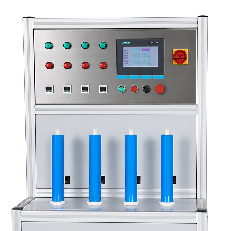
Compact multi-head dry screening
For household formats such as 1812, 2012, 3012 and 3013, confirm adapter coverage, active head logic, loading time, saved recipes and the data expected from each test position.
Review the household vacuum testing machine
Large-format controlled testing
For 2540, 4021, 4040 and 8040 elements, verify the actual two-group operating logic, fixture interfaces, 30 to 40 second reference cycle, traceability and safe handling of larger products.
Review the industrial vacuum testing machineBefore requesting a proposal, provide element drawings, test-port geometry, expected product mix, shift output, utilities, floor layout, required records, local electrical and safety requirements, reference samples and the intended FAT method. A supplier cycle claim should be verified with your actual adapters and representative elements.
RO Membrane Element Leak Testing FAQ
Is dry vacuum testing more sensitive than water immersion?
Not automatically. Sensitivity depends on the equipment, connected volume, pressure differential, timing, instruments, fixture, element construction and validation samples. Dry vacuum is easier to automate and quantify, while immersion can provide visual location evidence. Compare demonstrated detection capability on your actual products.
Can a vacuum test show the exact leak location?
A standard pressure-response screen generally indicates that the complete connected circuit failed its limit; it does not identify the exact location by itself. First rule out fixture leakage, then use an approved localization method if root-cause evidence is needed.
Can water immersion damage an RO membrane element?
Water contact is not automatically damage, but it changes the handling state and may introduce drying, water-quality, contamination, storage and segregation requirements. The approved process should define whether the element can be immersed at that production stage and how it is dried and released afterward.
What pressure and test time should an RO element use?
There is no universal pressure and time that fits every element and fixture. Develop the recipe using safe product limits, known-good samples, representative defects, normal production variation and measurement-system capability. Control stabilization and measurement time separately.
Should every rejected element be tested again?
Use a documented retest rule. A common approach is to verify the fixture, clean and reseat the product, then allow one controlled repeat while retaining both results. Unlimited repeats weaken traceability and can hide fixture or process instability.
Does a leak-test pass confirm salt rejection and permeate flow?
No. Leak testing screens air-tightness or reveals visible leak paths under the selected method. Hydraulic performance requires separate salt-rejection and flow testing under defined feedwater, pressure, temperature and recovery conditions.
Method Development References
- ASTM E515-11(2022), Standard Practice for Leaks Using Bubble Emission Techniques. A general bubble-emission reference, not an RO element acceptance standard.
- ASTM E2930-13(2021), Standard Practice for Pressure Decay Leak Test Method. A general pressure-decay reference for method design; it is not specific to RO elements or dry vacuum equipment.
- ISO 20484:2017, Non-destructive testing – Leak testing – Vocabulary.
Compare RO Membrane Testing Equipment Around Your Product and Acceptance Method
Share your element formats, test interfaces, shift output, inspection stage and required records. WECOME can help separate screening, localization and hydraulic-performance requirements before equipment is specified.
Compare RO membrane testing equipment
Bessie has 10+ years of experience in RO membrane materials and water treatment supply chains. At WECOME, she helps manufacturers and system integrators worldwide source the right membrane components — from feed spacers and permeate carriers to NSF-certified adhesives — backed by hands-on technical support.