
RO membrane ultrasonic spot welding and three-side gluing are separate operations. In the WECOME configuration discussed here, ultrasonic welding fixes the permeate carrier fabric at 4-6 points. Three-side adhesive application is a separate operation in the membrane-sheet and feed-spacer assembly. A point-weld pattern is not a continuous adhesive seal, and the two operations should be specified separately when selecting equipment.
Configuration scope: The 4-6-point detail comes from WECOME’s clarification of the equipment discussed in this guide. It is not a universal weld count, weld-location drawing or setting for every RO membrane production line.
What Is the Difference Between Point Welding and Gluing?
Both operations appear in membrane-leaf preparation, but they act on different parts of the assembly and require different controls. Treating them as one function can lead to an incomplete machine specification or an incorrect production description.
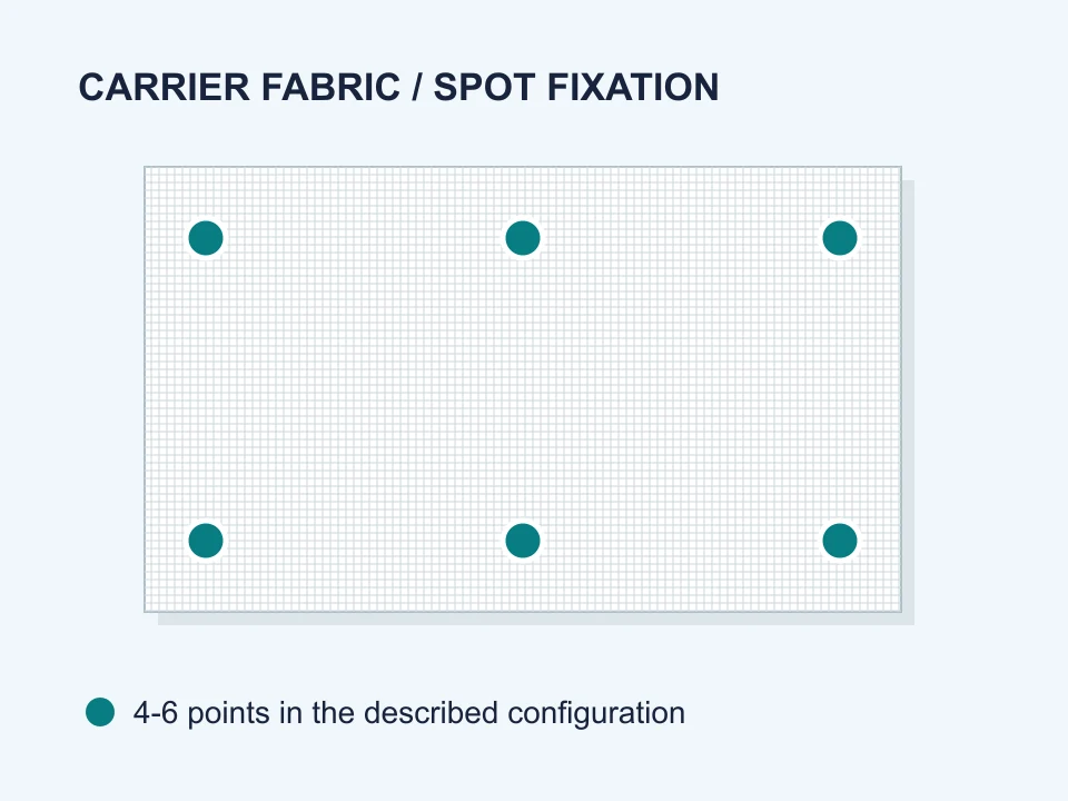
Ultrasonic point welding
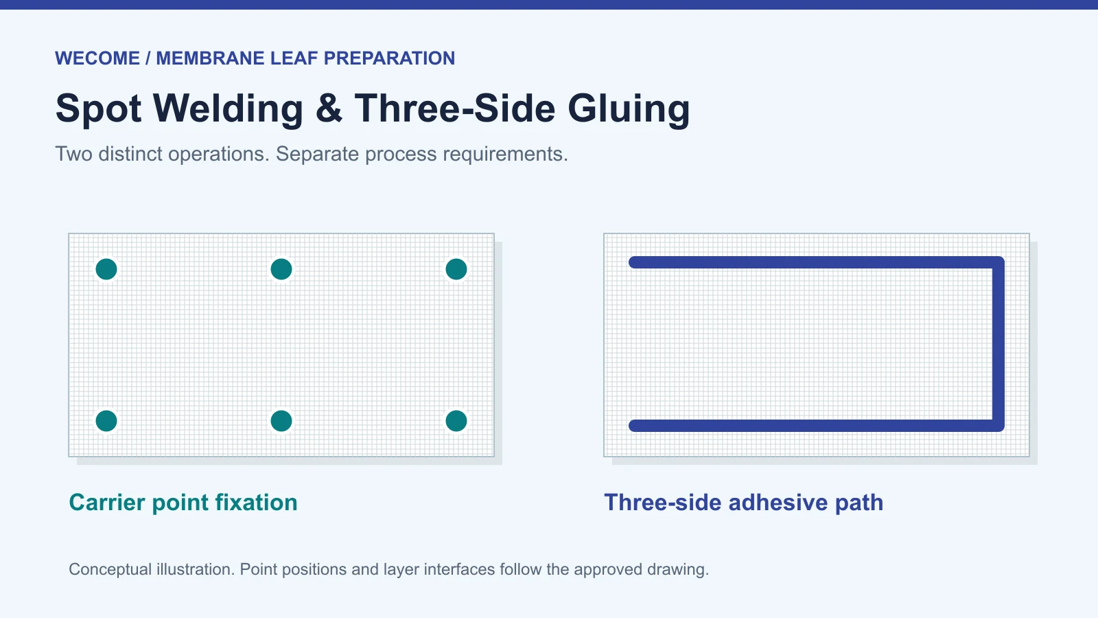
Discrete welds fix the carrier fabric at selected positions. The confirmed example uses 4-6 points.
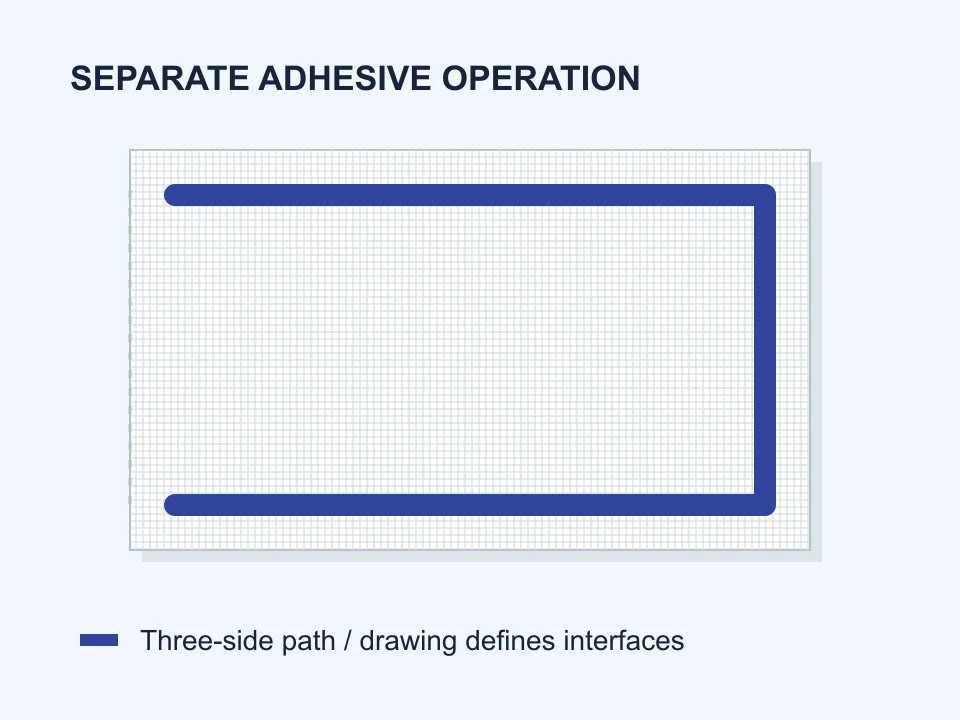
Three-side adhesive application
A controlled adhesive path is applied along three edges during the membrane-sheet and feed-spacer assembly operation.
Point weldingSeparate, localized weld points.
GluingAn adhesive path along three sides of the assembly.
Point weldingCarrier material, layer arrangement, point count, positions and approved tooling.
GluingMaterial stack, adhesive grade, mixing method, glue path and cure conditions.
Point weldingFixation, position and local fabric condition after welding.
GluingDispensing consistency, path continuity, working time and cure.
Point weldingThat a complete membrane envelope is sealed or that finished-element performance is acceptable.
GluingThat the carrier has the required point-weld pattern or that every finished element will pass testing.
Why Specify the 4-6 Weld Points Separately?
A request for a permeate carrier cutting and welding machine should identify both functions. Cutting establishes the required piece dimensions; the welding operation provides the specified point fixation. The words “cutting and welding” alone do not define the number or location of the welds.
For the configuration clarified by WECOME, the carrier fabric is welded at 4-6 points. The supplier and buyer still need a drawing showing the material arrangement and intended point positions. Do not convert this example into an assumed six-head machine layout or a fixed six-point recipe.
For an industrial equipment discussion, review the carrier trimming and ultrasonic welding machine with the actual material sample and required assembly drawing.
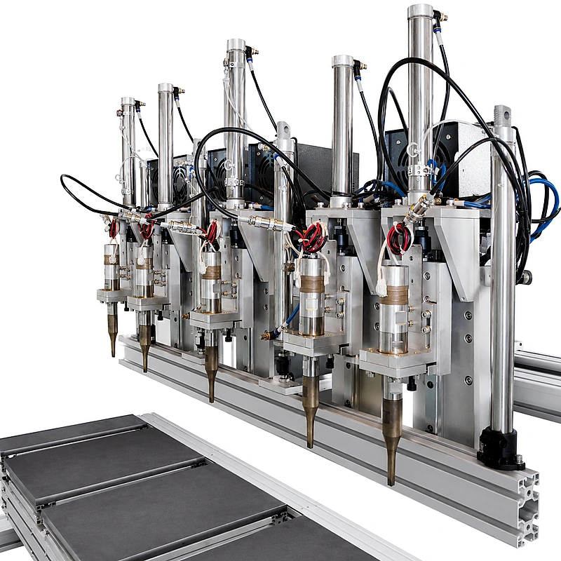
For general technical background, Dukane describes ultrasonic joining as a process involving contact, vibration, pressure and cooling. That principle does not establish a suitable recipe for a particular carrier fabric. Material compatibility and settings still require a trial.
Three-Side Gluing Needs Its Own Specification
WECOME distinguishes the carrier point-welding operation from three-side gluing in the membrane-sheet and feed-spacer assembly. Keep the adhesive requirements in a separate part of the production specification rather than assuming that an ultrasonic welding station also meters or dispenses glue.
Start with the approved layer drawing and glue path. Then identify the adhesive, mixing ratio, dispensing equipment, usable working window and cure conditions. For membrane-leaf adhesive selection, see the RO membrane PU glue specifications. Use the selected grade’s current technical data rather than transferring a ratio or cure time from another formulation.
Specify the interface, not just the words “three sides.” The drawing must identify the surfaces being bonded, the adhesive position and the intended flow paths. The schematic above explains the shape of the operation; it does not replace that drawing.
A complete equipment proposal should also state whether glue application is manual, handled by a separate dispensing station or integrated into the agreed rolling system. A machine’s welding capability is not evidence that it includes an adhesive system.
Use the Correct Material Names in the Drawing
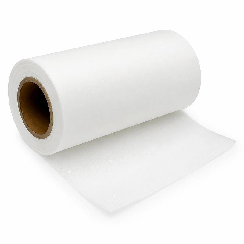
Permeate carrier fabric, often called tricot, and feed spacer mesh are different materials. Do not describe both simply as “mesh” in a purchase order.
Label each material on the assembly drawing and identify the sample supplied for testing. If your workshop uses a local name, add the English material name and a photograph so the equipment supplier can confirm what will actually be processed.
The existing carrier fabric inspection guide covers incoming material and conversion checks in detail. This article addresses the separate roles of point welding and adhesive application.
What Should the Sample Trial Demonstrate?
Evaluate the two operations separately before checking the assembled element. A visually acceptable weld or glue path is useful evidence, but neither alone is a finished-product release decision.
1. Point position and fixation
Compare the weld count and positions with the released drawing. Check that the fabric stays positioned through the intended handling steps.
2. Fabric condition
Inspect for local damage, excessive deformation or loose material around the welded points. Agree on acceptable samples and the inspection method.
3. Adhesive application
Check mixing, the three-side path, dispensing consistency and time within the approved working window. Record the adhesive batch and cure conditions.
4. Complete-element validation
Review downstream assembly and the required integrity and hydraulic performance tests. Keep results linked to the material lots and production recipe.
Use the RO membrane element QC checklist to connect these observations with the factory’s wider release process.
What to Send for an Equipment Review
A useful enquiry distinguishes the carrier-welding requirement from the glue-dispensing requirement. Send:
- The target element format and dimensioned material-stack drawing.
- The carrier grade, sample, layer arrangement and required cut dimensions.
- The intended point-weld count and locations, with an accepted sample if available.
- The three-side glue-path drawing, adhesive grade and dispensing method.
- The target usable output, current handling steps and agreed acceptance checks.
This allows WECOME to review the material, tooling and equipment scope together without treating spot welding and gluing as interchangeable functions.
RO Membrane Welding and Gluing FAQ
Does ultrasonic point welding replace three-side gluing?
No. In the configuration described here, carrier fabric is fixed at separate weld points, while three-side adhesive application is a different assembly operation. Each needs its own specification and validation.
Does every carrier require 4-6 weld points?
No. This is the configuration detail supplied by WECOME for the equipment discussed here. The final count, positions and settings depend on the approved material arrangement and process drawing.
Does a cutting and welding machine automatically include glue dispensing?
No. Confirm the included modules and production responsibilities in the quotation. Glue dispensing may be a separate operation or part of another agreed system.
Can a weld photograph prove membrane sealing performance?
No. A photograph can document the pattern and visible condition. The required handling, assembly, integrity and hydraulic performance checks must be evaluated separately.
Technical Basis and Scope
The process distinction and 4-6-point configuration are based on WECOME’s equipment clarification. The drawings are original explanatory schematics, not shop-floor instructions. General ultrasonic joining background: Dukane, Ultrasonic Plastic Welding. This external reference does not validate WECOME’s specific point count, equipment configuration or membrane process.
Review Your Carrier Welding and Glue-Path Requirements
Send your carrier sample, weld-point drawing and three-side adhesive layout. WECOME can help clarify the required equipment functions before quotation.
Discuss Your Leaf Preparation Process
Bessie has 10+ years of experience in RO membrane materials and water treatment supply chains. At WECOME, she helps manufacturers and system integrators worldwide source the right membrane components — from feed spacers and permeate carriers to NSF-certified adhesives — backed by hands-on technical support.