

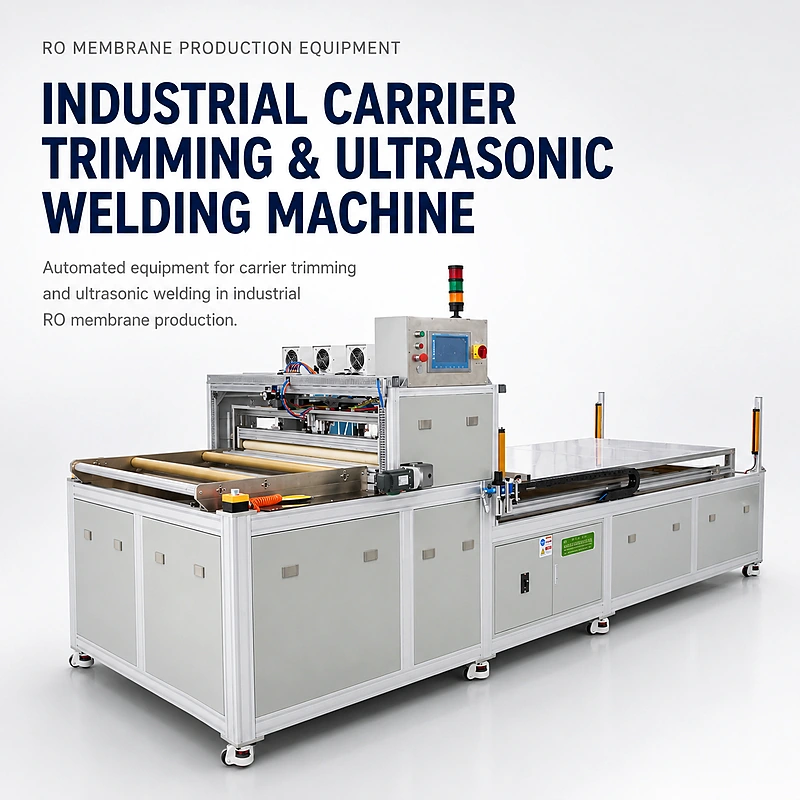

The WECOME Carrier Trimming & Ultrasonic Welding Machine automates web feeding, calibration, fixed-length cutting, indexed stacking, ultrasonic joining and finished-stack discharge for industrial spiral-wound membrane production.
Configured around 4040, 8040, 2540 and 4021 element programs, this industrial RO membrane carrier cutting and welding machine helps manufacturers prepare repeatable carrier or spacer assemblies before the rolling stage. Servo motion, PLC recipe control and adjustable welding parameters reduce manual measuring, cutting and layer-placement variation.
Automatic Carrier Cutting and Ultrasonic Welding for Industrial RO Production
The machine is designed for the material-preparation stage ahead of an industrial RO membrane rolling machine. After the production recipe is selected, the system manages roll tension, detects material conditions, feeds the web to length, cuts it, indexes the required stack pitch, applies ultrasonic welds and transfers the completed assembly to the receiving area.
This integrated sequence is more consistent than separate manual measuring, trimming and welding stations. It is particularly useful when an 8040 recipe requires many repeated layers and the position of every layer must remain controlled before spiral winding.
Integrated Cutting, Stacking and Welding Workflow
Load the roll
Install the specified web roll and select the approved element recipe.
Control tension
Air-shaft feeding and calibration stabilize the web before measurement.
Measure and cut
Servo feeding positions the programmed length for precision cutting.
Index the stack
Layer position follows the selected 4-30 mm stacking pitch.
Ultrasonic weld
Welding spacing and time are adjusted for the validated material.
Count and unload
The finished assembly transfers to the receiving tray for inspection.
Key Production Advantages
Integrated automatic sequence
Cutting, indexed stacking, ultrasonic welding, forming and unloading are coordinated in one production station.
Servo-controlled positioning
Precision feeding and tooling support repeatable cut length, end alignment and stack placement across production batches.
Adjustable ultrasonic process
Weld spacing and weld time can be tuned during sample validation to match the approved carrier or spacer material.
Material-condition monitoring
Connector or splice identification, material-shortage detection and slip monitoring help operators respond before defective stacks continue downstream.
Recipe-based format changes
PLC and touchscreen control simplify adjustment between compatible 4040, 8040, 2540 and 4021 production programs.
Reduced manual handling
Automatic measuring, cutting and stacking reduces repetitive operator work while retaining inspection and material-replenishment control.
Carrier Trimming & Ultrasonic Welding Machine Specifications
| Technical Item | Standard Reference |
|---|---|
| Product Name | Carrier Trimming & Ultrasonic Welding Machine |
| Primary Function | Automatic web feeding, calibration, fixed-length cutting, indexed stacking, ultrasonic welding and finished-assembly unloading |
| Compatible Element Formats | Industrial 4040, 8040, 2540 and 4021 membrane element programs |
| Processing Width | 500-1200 mm, adjustable within the configured range |
| Cutting Length | 300-2300 mm, recipe adjustable |
| Standard Roll Reference | Up to 800 mm roll diameter; 1100 mm reference net width. Confirm actual roll core, width and weight before manufacture. |
| Cutting and Stacking Precision | End cutting error ±1 mm; stack pitch 4-30 mm; specified cumulative error ≤1 mm |
| Production Reference | General multi-layer cycle: approximately 3-8 minutes depending on layer count and recipe. Supplied references: 8040, 25 layers in approximately 4 minutes; 4040, 5 layers in approximately 1 minute. |
| Operation | Automatic production sequence with operator loading, recipe selection, monitoring and collection |
| Control Mode | PLC and touchscreen HMI; foot-switch and production-count functions may be included in the approved configuration |
| Electrical Supply | AC 220 V / 4 kW |
| Air Supply | 0.6-0.8 MPa clean, dry compressed air |
| Main Machine Dimensions | 6250 × 1750 × 1950 mm (L × W × H) |
| Carrier Roll Frame Dimensions | 1244 × 1580 × 736 mm (L × W × H) |
| Equipment Weight | Approximately 650 kg |
| Packing Reference | Three listed package envelopes: 1950 × 710 × 830 mm; 2320 × 1800 × 2120 mm; and 1910 × 1320 × 1480 mm |
| Model Number | Project-specific; confirm on the signed technical specification and quotation |
The supplied main-machine dimension has been standardized as 1750 mm wide. Electrical load, layout, package split, roll capacity, cycle time and component brands must be reconfirmed in the final technical agreement because tooling and automation scope can change by project.
Production Timing and Capacity Planning
Large industrial element reference
A supplied reference recipe for a 25-layer 8040 carrier or spacer assembly. Final timing depends on cut length, indexing pitch, weld pattern, roll handling and discharge settings.
Shorter stack reference
A supplied reference for a five-layer 4040 program. It should be verified using the customer’s actual material and approved welding sample during acceptance testing.
The general 3-8 minute range applies to different multi-layer programs. Capacity should be calculated from the approved layer count, web length, stack pitch, weld positions, loading interval, inspection time and planned shift utilization.
What This Machine Does – and What It Does Not Do
Designed for industrial material preparation
- Measures and cuts the specified carrier or spacer web
- Builds repeatable layer stacks at a programmed pitch
- Applies validated ultrasonic weld positions
- Prepares assemblies for downstream industrial rolling
Separate downstream processes
- It does not trim cured ends of a finished membrane element
- It does not perform vacuum integrity or hydraulic performance testing
- It does not replace membrane sheet cutting and folding equipment
- It is not a final assembled-filter inspection station
Where This Industrial Machine Fits Best
4040 and 8040 RO factories
Routine industrial spiral-wound element production that requires repeatable multi-layer material preparation.
2540 and 4021 product programs
Additional industrial or commercial formats after dimensional, material and tooling confirmation.
Production-line expansion
Replacing separate manual cutting, stacking and welding work with an integrated automatic station.
OEM and ODM manufacturing
Recipe-controlled preparation for several customer formats with documented changeover requirements.
New-element validation
Production-representative trials for a new layer count, material width, weld pattern or element construction.
Turnkey industrial projects
Integration before rolling, curing, end trimming, integrity testing and exterior reinforcement stations.
Quality Checks Before Industrial Membrane Rolling
Dimensional and stacking checks
- Web width, cut length and end squareness
- Layer count and sequence against the recipe
- Stacking pitch and cumulative registration
- Material splice, slip and shortage alarms
Welding and release checks
- Weld position, spacing and visual continuity
- Validated weld strength without material damage
- Clean edges without excessive deformation
- Output count and accepted stack identification
Add these checks to the plant’s RO membrane element quality control checklist. The acceptance method and sampling frequency should be agreed before FAT.
Configuration, Acceptance and Delivery
| Project Input | What WECOME Needs to Confirm |
|---|---|
| Element Program | 4040, 8040, 2540, 4021 or project-specific format; required layers per assembly and target shift output |
| Material Definition | Permeate carrier or feed spacer name, construction, thickness, width, roll OD, core ID, roll weight and representative sample |
| Cutting Recipe | Finished cut length, width, end tolerance, stack pitch and layer-registration requirement |
| Welding Recipe | Weld positions, spacing, time, strength criterion and acceptable visual standard |
| Utilities and Layout | Confirmed voltage/frequency, clean dry air capacity, access route, installation footprint and upstream/downstream interfaces |
| FAT Samples | Customer material trial, dimensional report, welded-sample approval, alarm checks, recipe changeover and agreed cycle demonstration |
| Documentation | Approved layout, technical specification, operation manual, electrical information, maintenance guidance and packing list |
| Packing and Shipping | Modular export packing based on the final machine layout; package quantity, dimensions and gross weight confirmed before shipment |
Frequently Asked Questions
What does a carrier trimming and ultrasonic welding machine do?
It automatically feeds, measures and cuts the specified industrial RO carrier or spacer web, builds the programmed layer stack, applies ultrasonic welds and unloads the prepared assembly for downstream membrane element rolling.
Which RO membrane element formats can the machine support?
The supplied range covers 4040, 8040, 2540 and 4021 industrial membrane programs. Final compatibility depends on web width, cut length, layer count, stacking pitch, roll dimensions and the approved tooling configuration.
Does the machine process permeate carrier or feed spacer?
That must be confirmed from the customer’s element drawing and material sample. Permeate carrier and feed spacer perform different functions in a spiral-wound element, so WECOME confirms the exact web, weld position and tooling before quotation.
How fast is the carrier cutting and welding cycle?
Cycle time changes with the number of layers and recipe. Supplied references are approximately four minutes for a 25-layer 8040 program and one minute for a five-layer 4040 program, while general multi-layer programs may take approximately three to eight minutes.
What cutting and stacking accuracy is specified?
The supplied reference is plus or minus 1 mm cutting error at both ends, an adjustable stacking pitch of 4-30 mm and a specified cumulative stacking error of no more than 1 mm. The acceptance method must be defined in the signed technical agreement.
Can the ultrasonic welding settings be adjusted?
Yes. Welding spacing and time can be configured for the validated material and assembly design. Sample trials are required to confirm weld position, holding strength and the absence of web damage.
Can this machine connect to an industrial RO membrane production line?
Yes. It is normally positioned before industrial rolling and can be supplied as a standalone station or integrated into a turnkey line with rolling, curing, trimming, vacuum testing and reinforcement equipment.
What information is required for an accurate quotation?
Provide the target element formats, layer count, carrier or spacer drawing, roll dimensions, material samples, cut sizes, stacking pitch, weld pattern, target capacity, plant voltage, compressed-air conditions and available installation layout.
Related Equipment and Technical Resources
Confirm the Web, Stack and Welding Recipe
Send your industrial element drawing, carrier or spacer sample, roll dimensions, layer count and target output. WECOME will review the tooling, layout and acceptance plan before quotation.