
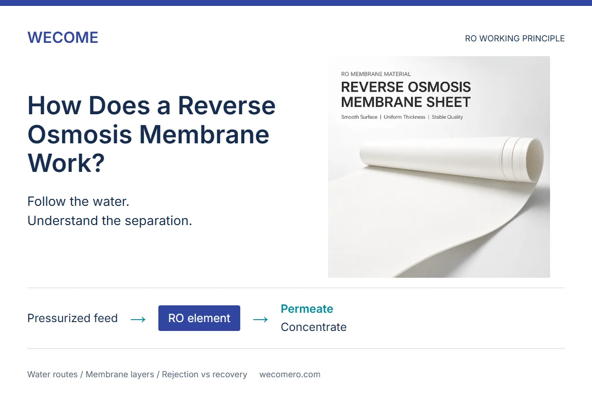
How does a reverse osmosis membrane work if dissolved salt is too small to see? The useful answer is not simply “a very fine filter.” It is a pressure-driven separation, followed by two different water routes inside the element. Understanding both explains why membrane sheet, spacers, seals and operating conditions all matter.
A reverse osmosis membrane uses a pressure difference to move water through a selective barrier while restricting the passage of many dissolved substances. The water that crosses the membrane becomes permeate. The remaining feed water carries a higher concentration of rejected salts away as concentrate. In a spiral-wound element, those streams travel through separate channels.
This guide explains the working principle of common spiral-wound RO elements. It is not an operating procedure, a drinking-water safety assessment or a performance guarantee for a particular membrane grade.
What is the concept of reverse osmosis?
With a suitable semipermeable membrane between two solutions, natural osmosis tends to move water from the more dilute side toward the more concentrated side. A sufficiently large opposing pressure difference reverses that net water movement. This reversal is the concept behind reverse osmosis. Nitto illustrates the distinction between natural osmosis and pressure-driven RO. [1]
Why does an RO membrane need pressure?
Pressure supplies the driving force for separation. It must overcome the opposing osmotic effect and provide useful water flow through the membrane. The relevant quantity is not just the feed gauge reading: pressure on the permeate side also matters. Asahi Kasei’s membrane-separation overview explains why an applied pressure above the osmotic pressure is required for RO. [2]
For someone comparing materials or elements, “tested at the same pressure” is therefore an incomplete statement. Ask where pressure was measured and whether the permeate outlet condition was the same. A reference test with an open outlet is not directly comparable to a test with appreciable product-water backpressure.
Does reverse osmosis require boiling or evaporation?
No. RO separates liquid water through a membrane; it does not use evaporation and condensation as its separation step. A membrane element is also not an entire treatment system. Pumps, pretreatment, instruments, controls and any required downstream treatment have separate jobs. Specifying a membrane alone does not define the quality or capacity of the complete installation.
Where does the water go inside a spiral-wound RO membrane?
Feed water moves along the outside of membrane envelopes; permeate collects inside those envelopes. The membrane separates the two routes. Winding the leaves around a collection tube packages a large working area into a cylindrical element without intentionally mixing the streams.
1. How does feed water reach the membrane surface?
Feed enters the element and travels through channels maintained by feed spacer mesh. In the usual spiral-wound arrangement, this feed-to-concentrate route runs along the element’s length. The mesh does not perform the dissolved-salt separation; it helps establish the channel through which water reaches the membrane surface.
2. What becomes permeate?
Some water crosses the membrane into the leaf envelope. A permeate carrier inside the envelope provides a drainage route toward the perforated collection tube. Product water then leaves through that tube. The feed spacer and permeate carrier therefore serve different sides of the membrane and are not substitutes.
3. What happens to the salts that do not pass through?
They largely remain in the feed-side stream, which becomes more concentrated as water is removed. That stream exits as concentrate, also called reject or brine. DuPont describes this crossflow arrangement: part of the incoming water crosses the membrane while the rest flows along it. [3]
A common misunderstanding is that an RO element stores all the removed salt until it is full. That is not the intended separation mechanism. Dissolved salts normally leave in concentrate, although deposits and fouling can still develop. Do not block or arbitrarily reduce concentrate flow to force more water through the membrane.
For the complete component inventory and assembly view, see our RO membrane element structure guide. This article follows the water routes; that resource identifies the individual parts.
What actually performs the separation in a TFC membrane sheet?
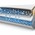
In a common polyamide thin-film composite, or TFC, RO membrane, a thin selective layer is supported by a porous supporting layer and a backing fabric. Toray illustrates this layered arrangement using polyamide, polysulfone and polyester backing. Exact chemistry and dimensions depend on the product; a generic layer diagram is not a specification for every RO membrane. [4]
Is an RO membrane just a mesh with very small holes?
That explanation is too crude for material selection. The visible feed-spacer openings are not the membrane’s separation barrier, and a nominal “pore size” does not tell a buyer how every dissolved substance will behave. Molecular-scale transport in RO is a specialized research topic; published work continues to examine how best to model it. For purchasing, use the grade’s measured rejection and flow under stated conditions, rather than inferring performance from a sieve analogy. [5]
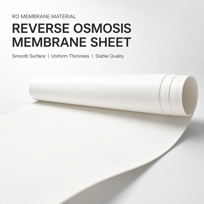
Manufacturing an element? Start with the RO membrane sheet specifications and supply options, then check the intended feed water and element acceptance requirements. A sheet sample and a completed element are different test specimens: passing one evaluation does not automatically approve the other.
Why do the spacer and carrier matter if the membrane does the separation?
The membrane needs both access to feed water and a route for the water that has crossed it. The supporting channel materials help provide those routes. Their roles are easiest to understand by keeping the two sides separate.


| Material or feature | Role in the water route | Question for an element-production project |
|---|---|---|
| Membrane sheet | Selective barrier between feed and permeate. | Which grade and test conditions define the required flow and rejection? |
| Feed spacer | Maintains a feed-side channel between leaves. | Is its geometry approved for this leaf stack and hydraulic duty? |
| Permeate carrier | Provides drainage inside the envelope toward the tube. | Is the carrier specification compatible with the membrane and leaf design? |
| Leaf seals and tube interface | Keep feed from bypassing the membrane into the permeate route. | How are bonding, integrity and dimensional fit verified? |
For a buyer, the practical takeaway is to qualify a material stack, not to collect unrelated “best” components. Record the approved combination and then test finished elements. Our feed spacer thickness and pressure-drop guide develops the feed-channel selection questions without treating one mesh dimension as a universal solution.
Are salt rejection, recovery and water flow the same thing?
No. Rejection describes separation, recovery describes how feed flow is divided, and permeate flow describes output. A percentage without its definition is easy to misread. The following independent examples use invented numbers to explain the arithmetic, not to predict a WECOME product’s performance.
How is observed salt rejection calculated?
Observed rejection (%) = [1 – (Cp / Cf)] × 100
Cp is permeate concentration and Cf is feed concentration, measured on a consistent basis. Example: 10 mg/L permeate and 500 mg/L feed gives [1 – (10 / 500)] × 100 = 98%.
Identify the solute or measurement basis and sampling locations. A conductivity-derived TDS comparison is a practical estimate, not a measurement of every individual contaminant. Keep meter conversion factors and temperature compensation consistent. The observed result is also not the same as an intrinsic membrane property measured at the membrane surface.
How is recovery calculated?
Recovery (%) = (permeate flow / feed flow) × 100
Example: 20 L/h permeate from 100 L/h feed gives 20% recovery. For a steady single-pass example with no other flows, concentrate is 80 L/h. This is an arithmetic illustration, not a recommended setting.
Thus, 98% salt rejection does not mean that 98% of incoming water becomes product water. Likewise, a high recovery does not establish a high rejection. DuPont’s technical manual defines the performance quantities and discusses their dependence on test and operating conditions. [6]
What is the difference between flow and flux?
Permeate flow is the volume produced per unit time. Flux expresses that output per unit of effective membrane area. Two elements can have different total outputs partly because they contain different working areas. When comparing quotes, check the units, effective area and test basis before treating an output number as evidence of a better membrane.
Why can the same membrane produce different results?
A membrane’s observed performance belongs to a set of conditions. Temperature, salinity, pressure and recovery can change a reading even when the material itself has not changed. Instrumentation also matters: a comparison is only as useful as the measurements behind it. Yokogawa discusses the importance of monitoring these operating variables. [7]
| Variable | Why it matters | What to record |
|---|---|---|
| Pressure conditions | The feed and permeate sides together determine the hydraulic driving difference. | Feed, concentrate and permeate readings, with gauge locations. |
| Water temperature | Colder water generally produces less permeate under otherwise comparable conditions. | Measured temperature, not room temperature alone. |
| Feed concentration | More concentrated feed changes the osmotic opposition to water transport. | Feed composition or test solution and its measured concentration. |
| Recovery and flow balance | The feed becomes more concentrated as product water is removed. | All relevant flow rates; identify recirculation if present. |
| Element condition | Deposits, damage or internal leakage can change the result. | Baseline, conditioning history, integrity checks and maintenance history. |
This is why a low-flow complaint needs a test record before a material substitution. First compare like with like; use the applicable manufacturer’s normalization procedure where appropriate. Do not improvise a universal correction or raise pressure beyond approved limits to recover a headline output.
If product-water salt passage is the concern, use our RO membrane salt rejection test-failure guide for a separate investigation. A general working-principle article cannot diagnose an individual failed element.
Why are pretreatment and the rest of the system still necessary?
The membrane is one treatment stage, not a substitute for designing the whole process. Feedwater conditioning protects the element and helps keep it within its approved service conditions. Pentair describes sediment filtration, chlorine reduction and scale-control measures as examples of pretreatment used in RO systems. The appropriate arrangement depends on feedwater analysis and membrane compatibility. [8]
For manufacturing projects, separate three approvals: the raw material specification, the finished-element test and the complete system’s intended water-quality requirement. A material supplier’s data sheet is not proof that an assembled system meets every end-use requirement. Specify the required verification at the correct level rather than asking one test report to answer all three questions.
What else do people ask about how RO membranes work?
Does an RO membrane remove 100% of dissolved salts?
No. Rejection depends on the membrane, solute and test conditions. Use the specified performance for the actual grade and application; do not treat the term “reverse osmosis” as a guarantee of zero salt passage.
Does the feed spacer filter the salt out?
No. The spacer provides a feed channel. The membrane’s selective layer performs the separation. A mesh photograph cannot establish the salt rejection of a completed element.
Does every RO system need an electric pump?
It needs a sufficient pressure difference. Whether that requires a pump depends on the available supply pressure and the system’s specified operating conditions. The membrane itself does not generate pressure.
Does an 8040 element work differently from a household element?
Common spiral-wound elements share the same separation principle. Size, membrane grade, area, construction and operating limits differ. A shared principle does not make the elements interchangeable.
Is the central tube where the feed water is filtered?
No. In the arrangement described here, the central tube collects permeate after water crosses the membrane and travels through the carrier. Feed water follows a separate route through spacer channels.
Will a rolling machine make the selective membrane layer?
No. Element rolling assembles prepared membrane sheet and other materials into a wound element. Making the selective layer on membrane sheet is a separate manufacturing process. Define which process you need before requesting equipment.
Turning the working principle into an RO element specification?
For a material or element-production inquiry, send WECOME your target element format, intended feedwater conditions, required output and rejection, and the test basis you will use for acceptance. Include your current material specification or sample reference when available.
Discuss Your RO Material RequirementsSources and illustration notes
Diagrams are original simplified teaching illustrations, not product cross-section photographs, dimensional drawings or measured performance data. Product images are linked from WECOME’s existing product galleries. Numerical examples are illustrative and are not operating recommendations.
- Nitto: About Reverse Osmosis/Nanofiltration. Osmosis and the reversal of net water movement.
- Asahi Kasei: Principles of Membrane Separation. Pressure-driven separation.
- DuPont: Reverse Osmosis. Crossflow and performance context.
- Toray: RO Membrane Structure. Representative TFC layers; not a WECOME dimensional specification.
- Water transport in reverse osmosis membranes is governed by pore flow, not a solution-diffusion mechanism. Molecular-transport research context, not a product recommendation.
- DuPont FilmTec Technical Manual. Performance terminology and comparison conditions; follow the applicable product documentation for operating limits.
- Yokogawa: Factors Affecting Reverse Osmosis Operation. Operating variables and measurement.
- Pentair: What Is Reverse Osmosis and How Does It Work? Pretreatment and system context.

Bessie has 10+ years of experience in RO membrane materials and water treatment supply chains. At WECOME, she helps manufacturers and system integrators worldwide source the right membrane components — from feed spacers and permeate carriers to NSF-certified adhesives — backed by hands-on technical support.