

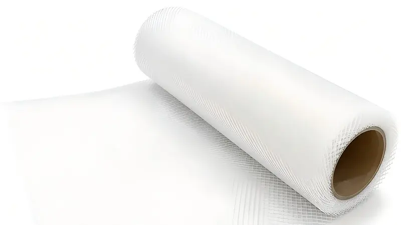
Understand how channel height, filament geometry and element construction interact before specifying an RO membrane feed spacer.
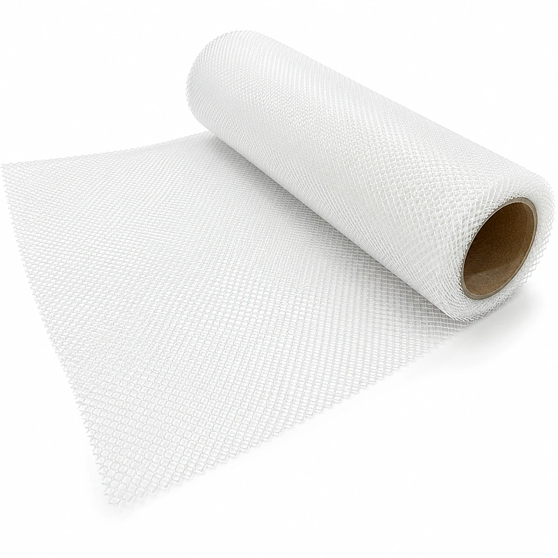
RO membrane feed spacer thickness helps define the feed-channel height, but thickness alone does not predict element performance. A more open channel may lower hydraulic resistance and tolerate some deposits better, while a thinner channel can support a more compact element construction. The real result depends on filament shape, mesh angle, orientation, feed velocity, water chemistry, pretreatment, recovery, membrane area and the way the element is rolled.
What Feed Spacer Thickness Actually Describes
The feed spacer separates adjacent membrane surfaces and creates the channel through which feed water travels toward the concentrate outlet.
In supplier literature, thickness is often stated in mil, where one mil equals one thousandth of an inch. For orientation, 28, 31, 34 and 46 mil correspond to approximately 0.71, 0.79, 0.86 and 1.17 mm. These values appear in published research on commercial spacer geometries, but they are not universal product grades and should not be treated as interchangeable.
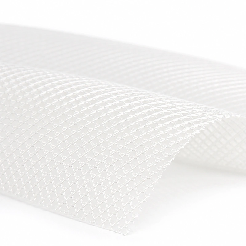
A thickness value should be read together with the mesh construction. Two spacers with similar nominal thickness can create different velocity fields and pressure losses when their filament diameter, crossing angle, strand shape, contact points or orientation differ.
Pressure Drop and Mixing Move Together, but Not in a Simple Line
A spacer is intentionally placed in the flow path. It keeps the channel open and promotes mixing, but its filaments also create drag.
Flow area
A wider or more open channel can reduce velocity and hydraulic resistance under the same volumetric flow, but the exact result depends on its geometry.
Local mixing
Filaments disturb the velocity profile and can improve transport near the membrane surface. Stronger disturbance may also require more pumping energy.
Orientation
PIV studies show that attack angle changes both mixing and pressure loss. The same spacer can behave differently when its orientation changes.
Operating point
Feed flow, viscosity, temperature, recovery and vessel staging determine where the element operates on its hydraulic curve.
Separate clean-channel pressure drop from pressure-drop rise during fouling
These are related but different questions. Clean-channel pressure drop describes the hydraulic resistance before significant deposition. Pressure-drop rise describes how that resistance changes as biomass, particles or scale accumulate.
Can a Thicker Feed Spacer Reduce Fouling?
Published pilot-scale and numerical studies report that a thicker or modified spacer can reduce the pressure-drop impact of fouling under the tested conditions. One pilot study observed fouling mitigation with the thicker spacer it evaluated, while a numerical study of commercial 28, 31, 34 and 46 mil geometries found that thicker or modified designs reduced the pressure-drop increase caused by modeled biofilm growth.
That evidence does not make thickness a universal antifouling specification. Deposits frequently develop around spacer filaments, and filament shape and biomass location can strongly affect the resulting restriction. Feed-water pretreatment, nutrient load, flux, recovery, crossflow, cleaning chemistry and operating discipline remain decisive.
| Question | Why it matters | Evidence to request |
|---|---|---|
| What feed water will the element treat? | Biological, particulate, organic and scaling risks do not respond identically. | Water analysis, pretreatment design, recovery and cleaning plan. |
| What is the clean hydraulic baseline? | A later pressure-drop rise is meaningful only when the original condition is documented. | Pilot or element test at defined flow, temperature and pressure. |
| Where do deposits accumulate? | Spacer contact points and low-velocity regions can become sensitive locations. | Autopsy, coupon inspection or validated flow study. |
| Can the channel be cleaned effectively? | Hydraulic access and cleaning chemistry both influence removal. | Cleaning procedure and post-clean normalized performance. |

Thickness Also Changes How the Element Is Built
The feed spacer is not only a hydraulic component. It is one layer in the spiral-wound stack and must pass through cutting, leaf preparation and rolling without destabilizing the element.
A change in spacer thickness can alter the radial build per wrap. If leaf count, membrane dimensions and other layers remain unchanged, finished diameter may move outside the approved range. The manufacturer may need to revise leaf configuration, tension, material lengths or tooling settings.
More radial build per wrap can reduce the number of leaves or membrane area that fits within a fixed outer diameter.
Mesh stiffness, curl, edge condition and friction influence tracking. The rolling recipe should be validated with the actual lot.
Spacer position must stay clear of critical glue paths and trimming allowances. A dimensional change may affect the released leaf drawing.
Before changing spacer grade, use the RO membrane roll diameter calculator for an initial geometry check, then confirm the result with a controlled sample build. The calculator supports planning; it does not replace a released production recipe.
Specify More Than Nominal Thickness
A useful purchase specification links material identity to dimensional control, conversion behavior and the target element design.
- Nominal thickness and tolerance
- Filament and mesh geometry
- Material resin and color
- Roll width, length, core and outer diameter
- Edge quality, curl and telescoping limits
- Cleanliness, packaging and lot traceability
- Orientation or cutting instructions
- Approved sample and change-notification rule

Use the WECOME feed spacer data sheet to organize specification fields, and review the broader RO membrane raw material selection guide when matching the spacer with membrane sheet, permeate carrier, central tube, adhesive and tape.
Compare Candidate Spacers Against the Same Operating and Build Conditions
A useful comparison holds the test method constant. Otherwise, a change in feed flow, temperature, membrane area or element construction can be mistaken for a spacer effect.
Begin with the approved element envelope: outer diameter, length, central tube, membrane sheet, leaf count and target active area. Then define one hydraulic test condition and one realistic fouling or cleaning challenge. Record both manufacturing observations and normalized element results. This prevents a candidate from appearing attractive hydraulically while creating an unacceptable rolling or yield problem.
| Selection context | Possible direction to investigate | What must be verified |
|---|---|---|
| Well-pretreated feed and compact element target | A thinner channel may be evaluated when maximizing packed membrane area is important. | Clean pressure drop, fouling margin, leaf count, finished diameter and stable rolling. |
| Variable or fouling-sensitive feed | A more open channel or alternative geometry may be evaluated for deposit tolerance and cleaning access. | Membrane-area trade-off, normalized pressure-drop rise, cleaning recovery and system energy. |
| Existing element or vessel platform | Start from the released design rather than substituting by nominal thickness. | Diameter, membrane area, pressure-vessel fit, hydraulic balance and field compatibility. |
| New supplier or revised mesh | Treat the material as a production change even when the nominal thickness is unchanged. | Geometry, resin, stiffness, cutting, tracking, glue-path clearance and sample-element results. |
The selected option should be the one that meets the complete acceptance window, not simply the candidate with the lowest clean pressure drop or the largest channel. For a B2B purchase decision, document the assumptions, test conditions and approved lot so the result can be repeated when production scales.
How to Qualify a Feed Spacer Before Mass Production
The most defensible choice is made through staged evidence, not a catalog comparison alone.
Define duty
Document feed water, element size, target diameter, membrane area, operating range and cleaning strategy.
Review data
Compare thickness tolerance, mesh construction, roll format, resin and change-control documents.
Inspect lot
Measure multiple positions and check width, edge quality, curl, contamination and roll condition.
Run conversion
Cut, fold and roll the actual material. Record feeding stability, alignment, tension and finished diameter.
Validate element
Use the appropriate integrity, hydraulic and field or pilot tests before releasing the revised bill of materials.
For feed streams with significant hardness and scaling risk, connect the spacer review to the complete brackish water RO application, including pretreatment, recovery and cleaning decisions.
Feed Spacer Thickness FAQ
Is a thicker RO feed spacer always better?
No. A thicker or more open channel may reduce hydraulic resistance or pressure-drop rise under certain fouling conditions, but it can also reduce the membrane area that fits inside a fixed element diameter. Geometry, flow, feed water and element construction must be evaluated together.
Does feed spacer thickness determine pressure drop?
It contributes, but does not determine pressure drop by itself. Filament shape, mesh angle, orientation, surface contact, flow rate, temperature and element construction also affect resistance.
Can two spacers with the same thickness be substituted?
Not automatically. Compare tolerance, mesh geometry, resin, stiffness, roll condition and conversion behavior, then run a controlled element build and the required performance tests.
What should incoming inspection measure?
Check thickness at multiple positions, width, roll condition, edge quality, contamination, curl, mesh consistency and lot identity against the approved drawing and sample.
Does a feed spacer prevent membrane fouling?
No. Spacer design influences hydrodynamics and deposit behavior, but pretreatment, operating conditions, water chemistry and cleaning practice remain essential.
References and Scope
- Park, H.-G. et al. Effect of feed spacer thickness on the fouling behavior in reverse osmosis process: A pilot scale study, Desalination 379 (2016), 155-163.
- Bucs, S.S. et al. Effect of different commercial feed spacers on biofouling of reverse osmosis membrane systems: A numerical study, Desalination 343 (2014), 26-37.
- Haidari, A.H. et al. Effect of spacer configuration on hydraulic conditions using PIV, Separation and Purification Technology 199 (2018), 9-19.
- DuPont Water Solutions. FilmTec RO element construction technical manual excerpt.
The research findings above describe the cited test conditions and should not be read as guaranteed performance for every spacer, element or water source. Final specifications require engineering review and application validation.
Need to Match Feed Spacer Geometry to Your Element Build?
WECOME supplies RO membrane feed spacer and supports manufacturers in reviewing dimensions, roll format, material compatibility and production trials.
Discuss Spacer Specifications
Bessie has 10+ years of experience in RO membrane materials and water treatment supply chains. At WECOME, she helps manufacturers and system integrators worldwide source the right membrane components — from feed spacers and permeate carriers to NSF-certified adhesives — backed by hands-on technical support.