

A practical framework for defining product scope, realistic capacity, process flow, automation, utilities, quality control and commissioning for a spiral-wound RO membrane element factory.
RO membrane factory planning should start with the elements you intend to manufacture and the released output you need, not with an equipment quotation. Define the product families, production recipe, bottleneck capacity, labor model, material flow, utilities, quality gates and ramp-up evidence first. Only then can each machine be sized and specified as part of one workable production system.
Why an Equipment List Is Not Yet a Factory Plan
A line can contain capable machines and still miss its output, quality or delivery target if the product mix, transfer steps and acceptance rules were never defined together.
A spiral-wound RO element is a coordinated construction of membrane leaves, feed spacer, permeate carrier, central tube, adhesives and finishing components. DuPont’s element-construction reference shows that the number of membrane leaves varies with element diameter and design. That basic fact has a direct factory consequence: changing the element format can change leaf dimensions, material handling, rolling time, curing, finishing, testing and labor demand.
The planning sequence should therefore run from market and product requirements toward equipment, rather than from available machine models back toward an assumed product. The seven decisions below form a practical sequence for an investor, factory owner or project manager preparing an RO membrane production line.
Fix the Product Scope Before Designing the Line
Begin with a controlled product-family matrix. List the element diameter and length, application class, number of leaves, target outer diameter, central-tube design, dry or wet membrane handling, outer-wrap method, brine-seal configuration, packaging and required performance test. A statement such as “household and industrial membranes” is too broad for equipment configuration.
Household formats such as 1812, 2012, 3012 and 3013 may share a production concept, but the recipe and tooling still need defined adjustment ranges. Industrial formats such as 2540, 4021, 4040 and 8040 introduce different material widths, leaf counts, element weights, rolling forces, handling needs and finishing operations. Trying to cover every format on one line can increase changeover time and create compromises that were invisible during quotation.
- Separate launch products from future products.
- Define the approved bill of materials for each family.
- Record dimensions and tolerances, not only trade names.
- State which tests release each product family.
- Identify recipes that require dedicated tooling or equipment.

Plan Released Output, Not Nameplate Cycle Time
A machine’s fastest cycle under demonstration conditions is not the same as daily released factory output. Production capacity must include product mix, shift length, planned stops, changeovers, operator attendance, material replenishment, curing constraints, first-pass yield, rework and final inspection. It must also be limited by the slowest connected operation, not multiplied from the fastest station.
A useful first-pass capacity model
This is a planning model, not a contractual output guarantee. Use product-specific observations and verify the final model during trials and factory acceptance testing.
Use the RO membrane production capacity calculator to test different shift, cycle-time and yield assumptions before fixing the line configuration. Run at least a base case, a realistic peak case and a constrained case with lower uptime or a more complex product mix.
Map Every Material and Process Transfer
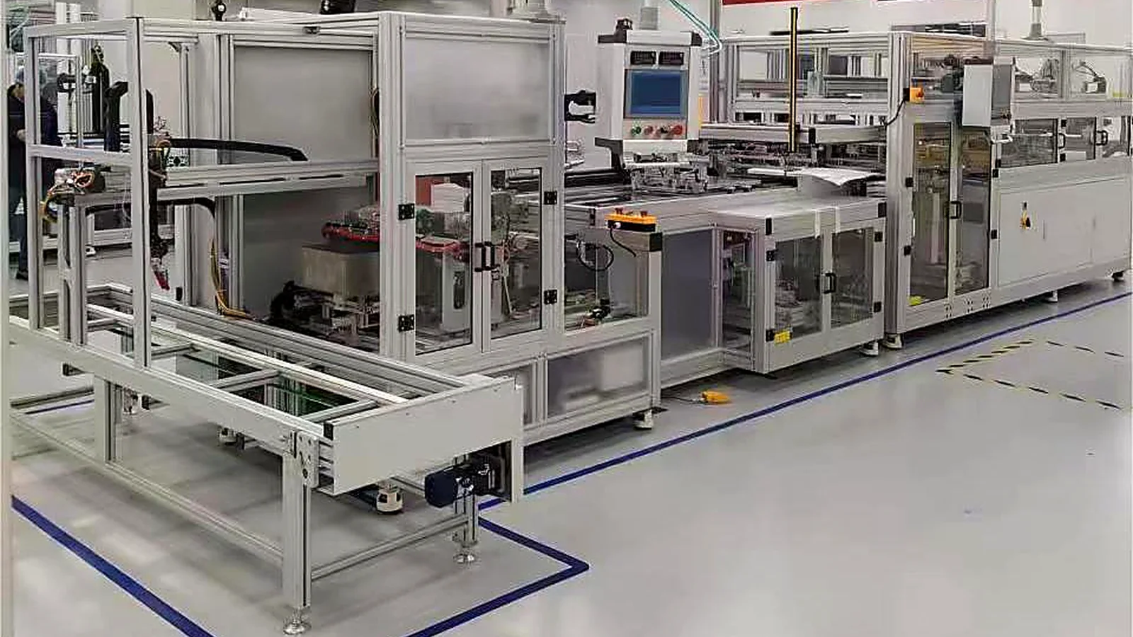
Draw the process from receiving through shipment and place each transfer between operations on the same map. For a spiral-wound line, the route may include incoming inspection, material conditioning, membrane and carrier preparation, leaf assembly, center-tube preparation, gluing and rolling, curing, trimming, outer wrapping, component assembly, dry integrity screening, hydraulic performance testing, labeling and packaging.
The exact sequence varies by product and factory. What matters is that every buffer, manual move, inspection hold and rework loop is visible. A machine may complete its own cycle quickly while the operator waits for material, transports work-in-process, cleans a glue path or resolves an upstream defect.
Receive and condition
Verify lot identity, roll condition, dimensions, storage status and release before conversion.
Cut, fold and prepare
Control usable width, leaf dimensions, alignment, welding or bonding and material sequence.
Glue, roll and cure
Manage the recipe, tension, glue path, central-tube alignment, outer diameter and curing status.
Finish, test and pack
Trim and assemble components, complete defined integrity and performance checks, then label by lot.
Choose the Automation Boundary Around Risk and Repetition
Higher automation is useful when it controls a repeated operation that affects consistency, throughput, safety or traceability. It is not automatically the best answer for a factory launching many low-volume formats. A practical design may automate material measurement, tension control, glue dispensing, rolling or data capture while retaining manual loading, recipe confirmation and visual inspection.
Compare operating models using the same product mix and output target. Include the number and skill of operators, training time, changeover effort, fault recovery, maintenance capability, spare-parts access and the consequence of one station stopping. Automation should remove a real constraint rather than move the constraint to material preparation, curing or quality release.
| Planning factor | Manual or assisted | Semi-automatic | Highly automated |
|---|---|---|---|
| Best fit | Pilot work, low volume or frequent special builds | Stable core products with controlled operator steps | Repeat product families with sustained demand |
| Main strength | Flexibility and lower initial complexity | Balance of repeatability, flexibility and investment | Cycle consistency, labor reduction and data integration |
| Main risk | Operator variation and difficult scaling | Transfer delays between automatic and manual steps | Higher integration, maintenance and stoppage impact |
| Evidence needed | Work instructions, skills matrix and inspection records | Cycle study, staffing map and controlled recipes | Line balance, uptime assumptions, recovery plan and technical support |
For the critical rolling stage, the RO membrane rolling machine selection guide explains how element size, output, material structure and automation level affect the equipment decision.
Design Layout, Utilities and Safety as One System
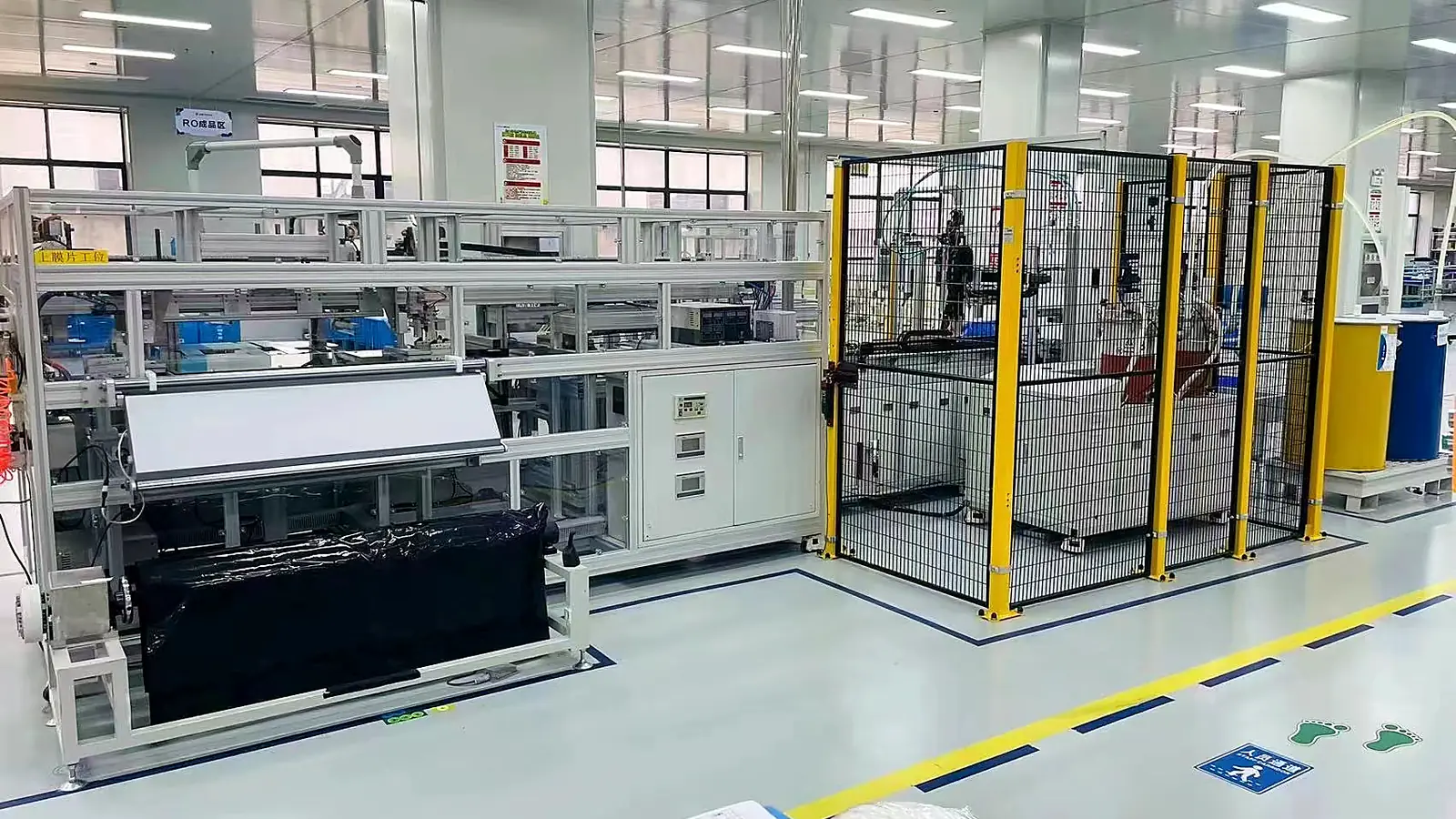
A layout drawing should show more than machine footprints. Include operator positions, material roll loading, component replenishment, work-in-process buffers, inspection holds, maintenance access, lifting paths, electrical cabinets, pneumatic and extraction connections, finished-goods movement and emergency routes. Reserve space for safe troubleshooting instead of placing equipment at its minimum transport dimensions.
Prepare a utility schedule for every machine and process. Confirm voltage, connected load, compressed-air quality and pressure, ventilation or local extraction, water and drain needs, network connections, ambient limits and any material-specific handling requirements. The final values must come from approved supplier drawings, safety data sheets, the factory risk assessment and local codes.
- Power, isolation and grounding
- Clean, dry compressed air
- Ventilation and adhesive handling
- Process water and drainage
- Temperature and humidity control
- Network and data retention
- Maintenance and lifting access
- Emergency and evacuation routes
Machinery safety should be reviewed through the equipment life cycle, including installation, normal production, cleaning, adjustment, fault recovery and maintenance. ISO 12100 provides a methodology for hazard identification, risk estimation and risk reduction. IEC 60204-1 addresses electrical, electronic and programmable electronic equipment of machines from the point of connection to the machine.
These standards do not replace destination-country requirements. Ask the supplier which standards the machine design follows, what protective devices are included, which residual risks remain, and what documentation is delivered for the intended market.
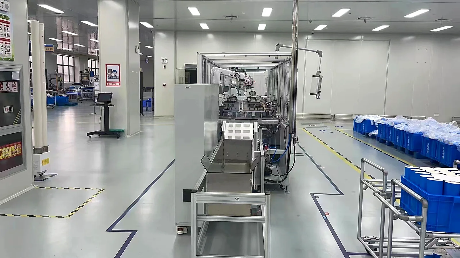
Use the RO membrane production line layout guide to turn the process map into a practical zoning and access plan.
Build Quality Gates Before the First Production Lot

Quality control is not a final test station added after the equipment is installed. The factory needs an acceptance plan for incoming materials, controlled process parameters, in-process inspection, nonconforming material, rework, final release and complaint traceability. Each product family should have a defined traveler or electronic record connecting the material lots and production recipe to the released element.
ISO 9001 frames quality management around planned and controlled processes, documented information, competence, performance evaluation and continual improvement. A factory does not need to make unsupported certification claims to use that process logic during planning.
Identify membrane sheet, spacer, carrier, tube, adhesives and components by supplier lot; check agreed characteristics and storage status.
Record leaf dimensions, alignment, welding or bonding, glue recipe, rolling parameters, diameter, curing status and visible defects as applicable.
Separate dimensional, visual, integrity and hydraulic-performance answers. Define sampling, limits, disposition and record retention for each.
Dry vacuum integrity screening can identify air-leak risk, but it does not replace salt-rejection and permeate-flow testing. Design the final QC route so that each method answers a stated quality question and the release record remains traceable to the product and batch.
Specify FAT, Installation, Training and Ramp-Up Evidence
Before requesting a firm quotation, issue a user requirement specification that describes products, materials, output assumptions, utilities, safety and destination standards, data needs, acceptance samples, documentation, training and service expectations. This gives suppliers one technical boundary and makes quotations easier to compare.
Factory acceptance testing should use agreed materials and representative product formats. The protocol should verify functions, tooling, recipes, safety devices, alarms, cycle observations, output handling and the records needed for approval. Site acceptance then confirms the installed utilities, interfaces and operation under the customer’s conditions.
Do not treat the first successful element as production readiness. Plan a ramp-up phase that trains operators and maintenance staff, establishes repeatable settings, challenges changeovers, closes defects and demonstrates released output across representative production lots.
Design freeze
Approve scope, layout, utilities, interfaces, acceptance protocol and document list before manufacture.
Factory acceptance
Verify functions and representative recipes with agreed materials, samples and recorded exceptions.
Site commissioning
Confirm installation, utility quality, safety, calibration, training and interface performance.
Production ramp-up
Demonstrate stable released output, changeover control, maintenance response and traceability.
What to Prepare Before Requesting an RO Membrane Factory Proposal
A complete inquiry does not need a finished engineering design. It does need enough facts for the supplier to avoid guessing about the production target.
- Launch and future element formats, dimensions and application classes
- Monthly demand by product family, shifts and peak-period assumptions
- Approved or intended membrane sheet, spacer, carrier, tube and adhesive
- Required process steps, test methods and release responsibilities
- Available building dimensions, columns, doors, loading access and floor limits
- Power, compressed air, water, drainage, ventilation and ambient conditions
- Preferred labor model, automation priorities and local technical capability
- Destination standards, language, documentation, FAT and training expectations
Use the RO membrane production line checklist to organize these inputs before comparing proposals. The checklist owns the detailed preparation workflow; this article explains why the decisions must be made in this order.
RO Membrane Factory Planning FAQs
How much space does an RO membrane factory need?
There is no reliable universal area. Space depends on element formats, output, automation, storage policy, curing and buffer time, testing scope, maintenance access, logistics and future expansion. Build the area from a scaled process-and-access layout after machine drawings are available.
Should a new factory start with household or industrial RO elements?
The decision should follow the target market, customer qualification requirements, material supply, technical capability and investment model. Household formats can involve smaller elements and different throughput economics, while 4040 and 8040 production requires wider materials, heavier handling and industrial tooling. Neither route is universally easier or more profitable.
Is a fully automatic line always more cost-effective?
No. Automation is cost-effective when demand, product stability, labor conditions, quality risk and technical support justify it. A highly automated line can be underused or difficult to recover after faults if the product mix changes frequently or local maintenance capability is limited.
Which machine determines RO membrane line capacity?
The answer depends on the product route and operating conditions. The bottleneck may be leaf preparation, rolling, curing, trimming, testing, manual transfer or quality release. Measure the complete route and use released output rather than selecting one machine’s shortest published cycle.
What should be completed before signing an equipment contract?
At minimum, align the product matrix, capacity assumptions, process responsibility, layout and utilities, machine interfaces, applicable standards, documentation, FAT and SAT protocols, training, spares, warranty, service response and change-control procedure.
Can one production line make every RO membrane element size?
Some equipment can adjust across several formats, but one line rarely covers every size without tooling, recipe and handling limits. Confirm each required format through drawings and representative trials, then reserve future formats as an expansion scope if they would compromise launch performance.
Reference Basis
- DuPont FilmTec Element Construction Manual excerpt, describing spiral-wound element construction and the role of membrane leaves.
- ISO 12100:2010 – Safety of machinery, providing principles and a methodology for machinery risk assessment and risk reduction.
- IEC 60204-1:2016, covering general requirements for electrical, electronic and programmable electronic equipment of machines.
- ISO 9001:2015 – Quality management systems, covering planned processes, documented information, competence, performance evaluation and improvement.
The references support general construction, safety and quality-management principles. Final equipment design, utilities, guarding, conformity and acceptance criteria must follow the approved supplier documentation, material safety information, customer requirements and laws applicable at the installation site.
Turn Your Product and Capacity Targets into a Workable Line Plan
Share your intended element formats, output, material structure, factory conditions and automation priorities. WECOME can help map the production route, equipment configuration, utilities, testing points and commissioning scope before individual machines are finalized.
Review Turnkey RO Membrane Production Line Support →For early engineering discussion, visit Technical Support & Engineering for RO Element Production.

Bessie has 10+ years of experience in RO membrane materials and water treatment supply chains. At WECOME, she helps manufacturers and system integrators worldwide source the right membrane components — from feed spacers and permeate carriers to NSF-certified adhesives — backed by hands-on technical support.