

RO Membrane Production Line Layout Guide
A good RO membrane production line layout lets material flow in one direction from goods-in to finished elements — with no backtracking. This guide shows the flow, the principles and the common mistakes.
- Goods-in & storage
- Cutting → gluing → rolling
- Wrap → trim → end caps
- Testing → pack → dispatch
Key Takeaways
- Lay the line out as a one-way flow, goods-in to dispatch.
- Group stations by production stage, in sequence.
- Leave dedicated space for QC and testing.
- Plan the footprint for your target output and growth.
Lay Out the Flow, Not Just the Machines
A production line is only as smooth as its material flow. The best layouts move material in a single direction — goods-in, cutting, gluing, rolling, wrapping, trimming, end caps, testing, packing, dispatch — so an element never doubles back. Backtracking wastes labour, mixes work-in-progress and hides defects.
This layout follows the same order as the production workflow. When you are ready to draw it, use the factory layout template.
Lay the Line Out in This Order
Each zone hands off to the next. Keep them in sequence so material flows one way.
Goods-in & material storage
Receiving and incoming inspection, with membrane stored correctly and stock close to cutting.
Cutting & preparation
Cut membrane, feed spacer and permeate carrier to size, feeding straight into gluing.
Gluing & rolling
Leaf making and winding on the rolling machine — the core of the line, with room to work around it.
Wrap, trim & end caps
Outer wrap (tape or fibreglass), trimming, and fitting end caps and brine seal for industrial sizes.
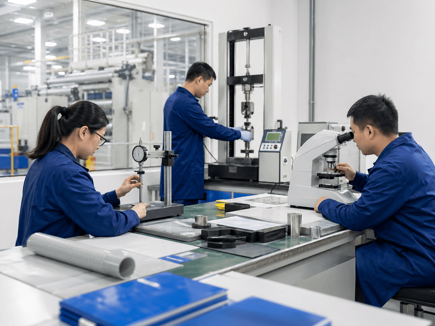
Testing & QC
A dedicated area for leak and performance testing, away from dust and traffic.
Packing & dispatch
Labelling, packing and finished-goods storage at the far end, ready to ship.
What Separates a Good Layout From a Poor One
| Aspect | Good layout | Poor layout |
|---|---|---|
| Material flow | One direction, no backtracking | Crisscrossing, doubling back |
| Station order | Matches the workflow sequence | Scattered by machine, not stage |
| Testing area | Dedicated, clean, separate | Squeezed into the main floor |
| Storage | Raw near cutting, finished near dispatch | Materials walked across the floor |
| Growth | Space left to add lines / shifts | Fully packed, no room to expand |
A Few Rules That Carry Most of the Benefit
You do not need a complex study to lay out a good line. Keep flow one-directional, put stations in workflow order, give gluing and rolling room to work, separate the test area, and leave space to grow. Confirm the line is fully equipped with the production line checklist.
For the floor plan itself, the factory layout planning template gives you a starting grid to adapt.
Layout principles
- One-directional material flow
- Stations in workflow order
- Work room around rolling
- Separate, clean test area
- Space reserved for growth
A Bad Layout Taxes Every Single Element
Layout is a fixed cost you pay on every unit — bad flow quietly adds labour and defects to the whole output.
Wasted Movement
Backtracking adds handling time to every element and ties up labour.
Mixed-Up WIP
Poor flow lets work-in-progress and batches mix, hurting traceability.
No Room to Grow
A packed floor forces a costly move or rebuild when you scale up.
Planning a new line layout?
Share your space and target output — our engineers will help you lay out the line and equipment, free of charge.
Line Layout FAQ
How should an RO membrane production line be laid out?
As a one-directional flow that follows the production sequence: goods-in and storage, cutting, gluing and rolling, wrapping and trimming, end caps, testing, then packing and dispatch. Material should never double back.
Where should the testing area go?
In a dedicated, clean area separate from the main production floor and away from dust and traffic, near the end of the line before packing. Leak and performance testing need stable, repeatable conditions.
How much floor space does a line need?
It depends on element sizes, automation level and target output. Plan the footprint around the material flow and your capacity target, and leave room to add lines or shifts as you grow.
What is the most common layout mistake?
Backtracking — arranging stations by machine instead of by workflow stage, so material crisscrosses the floor. It adds handling, mixes work-in-progress and hides defects.