
TECHNICAL GUIDE / SPIRAL-WOUND ELEMENT DIAGNOSTICS
An uneven membrane end face is a reason to investigate, not a reason to immediately blame the rolling machine. Before replacing a component or adjusting production settings, establish what moved, when it moved and what loading the element experienced.
What does RO membrane telescoping actually look like?
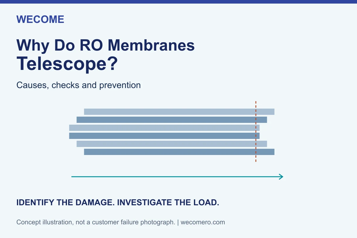
In a telescoped spiral-wound element, parts of the wound pack project axially beyond their intended end position. DuPont describes outer layers extending downstream relative to the remaining layers. Severe cases can damage membrane material or glue lines; the appearance alone does not establish the extent of internal damage. [1]
For an initial record, photograph the complete element, both ends and the affected area. Identify which end faced the feed and which faced the concentrate outlet before dismantling changes that information. Compare the condition with the approved drawing and any pre-shipment photographs, rather than comparing unrelated membrane brands.
Is every uneven end face evidence of telescoping?
No. An observation such as “the end looks uneven” is too broad for a diagnosis. Separate a protruding internal layer from a damaged cap, a trimming irregularity or an outer finishing defect. Keep your observation factual: state the location, direction and measured extent of the difference without assigning a cause.
| What you observe | What it does not establish | Evidence to collect |
|---|---|---|
| Internal layers project beyond the intended end plane | Whether the condition originated in manufacture, installation or operation | Both end views, original dimensions, serial number and operating history |
| A cap is displaced, cracked or visibly damaged | That replacing the cap will restore the complete element | Cap and shell details, assembly drawing and qualified inspection findings |
| Only the outer tape edge lifts | That internal membrane layers have moved | Close-up of the wrap seam and a separate view of the element end |
| Salt rejection falls with no confirmed displacement | That telescoping is the cause | Test conditions, conductivity readings, seal checks and performance history |
If poor rejection is the only symptom, start with the broader RO membrane salt-rejection test failure checklist. This article addresses suspected axial movement, rather than repeating every cause of a failed performance test.
Why check pressure drop instead of just feed pressure?
Feed pressure is one reading. Pressure drop compares readings at two defined locations. For the same measurement boundary, ΔP = feed-side pressure − concentrate-side pressure. Label whether the readings represent a vessel, a stage or another part of the system. A stage reading is not automatically a single-element reading.
For illustration, readings of 12.0 bar and 11.4 bar across one defined boundary give a difference of 0.6 bar. This arithmetic does not establish a safe operating limit. Compare the correct measurements with the applicable element and system documentation; do not borrow another model’s limit.
What does a rising differential-pressure trend tell you?
DuPont’s high-pressure-drop guidance identifies debris, foulants and scale in feed channels as possible reasons for increasing differential pressure at constant flow. It also discusses excessive flow and rapid startup pressurisation as relevant conditions. These are investigation paths, not conclusions to draw from one gauge reading. [2]
Put the pressure readings beside feed flow, concentrate flow, temperature and the time of the event. A reading taken after shutdown cannot reconstruct a short operating transient. Likewise, two readings taken at different flow conditions are not a controlled before-and-after comparison.
- Check the measurement boundary: mark the pressure-tap locations on a simple system sketch.
- Check the instruments: note gauge ranges, units, calibration status and any known sensor fault.
- Check the timeline: look for startup, cleaning, valve changes, maintenance or a pretreatment upset near the first observation.
- Check comparability: identify changes in flow, temperature and configuration before interpreting a trend.
Does biofouling prove the element telescoped?
No. Biofouling can increase resistance in the feed channel and is a documented contributor to differential-pressure problems, but a suspected foulant is not a mechanical-damage diagnosis. Keep three records separate: evidence of fouling, hydraulic measurements and evidence of layer displacement. [3]
Can an ATD end cap prevent every telescoping failure?
An anti-telescoping device supports the wound pack, but its presence is not permission to exceed the element’s operating limits. The component must also belong to the intended assembly. DuPont’s guidance for eight-inch elements specifically calls for a thrust ring supporting the outer diameter. A vessel thrust ring and an element ATD cap are different parts and should not be treated as interchangeable. [1]
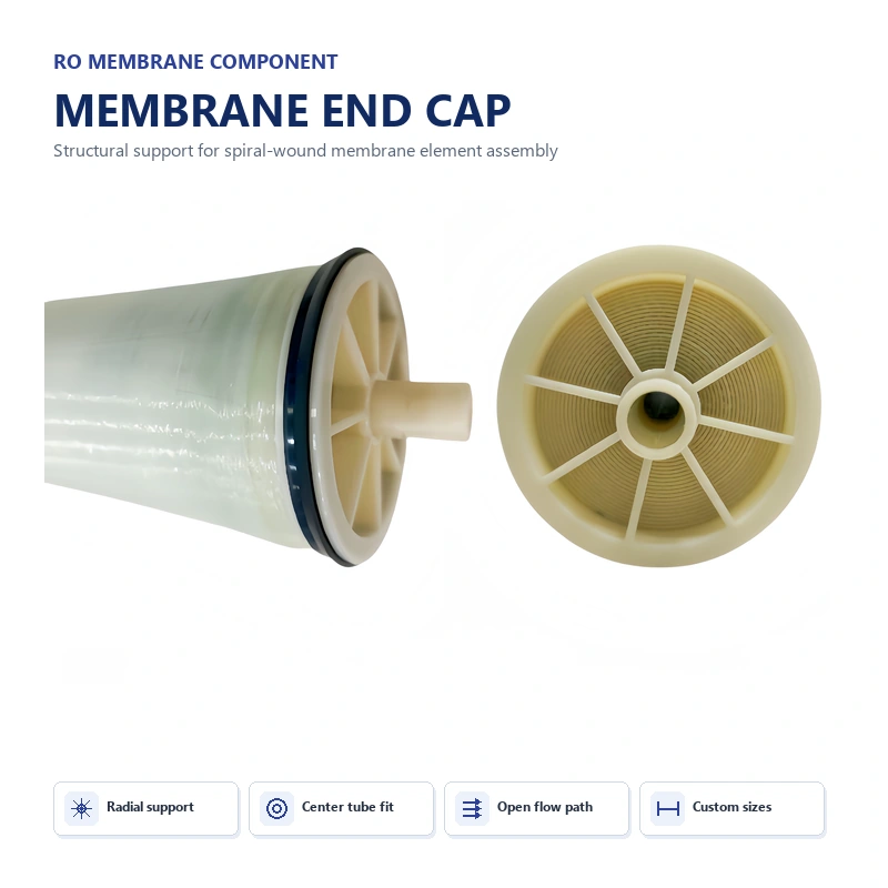
For a component review, compare the supplied part with the approved element assembly drawing. Ask which interfaces support the wound pack and which interfaces locate or connect other components. Nominal designations such as 4040 and 8040 are not a complete dimensional specification.
| Review item | Question for the responsible supplier or engineer |
|---|---|
| ATD part identity | Does this exact model and revision match the approved element build? |
| Element interfaces | Are the drawing-controlled cap, pack and tube interfaces correct? |
| Vessel support | Does the installed support arrangement match the vessel and element instructions? |
| Condition | Is there visible damage or a change from the recorded installation condition? |
| Installation record | Were orientation, loading and any required spacing arrangements documented? |
The ATD end cap product page is the place to compare supplied component options. Use the present guide to organise the failure investigation. Replacing one part without checking the assembly and loading history may leave the original problem unresolved.
What should manufacturers check before blaming field operation?
A useful investigation keeps the manufacturing and operating evidence open at the same time. “It passed the factory test” does not explain a later event, just as “it failed in service” does not prove a factory defect. Match the returned element’s serial number to its production and release records.
The checklist below is an evidence-gathering framework, not a list of proven causes. Do not change winding tension, adhesive or cap design simply because one item appears in the table.
| Manufacturing record | What to compare | Why retain it? |
|---|---|---|
| Approved recipe and revision | Material stack, dimensions and component identities | Establishes the intended build rather than a remembered specification |
| Rolling setup | Recorded settings, calibration and operator sequence | Allows a controlled comparison with a known conforming batch |
| Adhesive processing | Specified mix, working conditions and cure records | Checks compliance with the approved process without assuming a universal cure time |
| Finishing and assembly | End-face photographs, final dimensions and support components | Distinguishes a pre-existing condition from a later change |
| Release testing | Method, conditions, acceptance result and instrument identity | Shows what was actually tested and what the test did not cover |
Does buying a different rolling machine solve the problem?
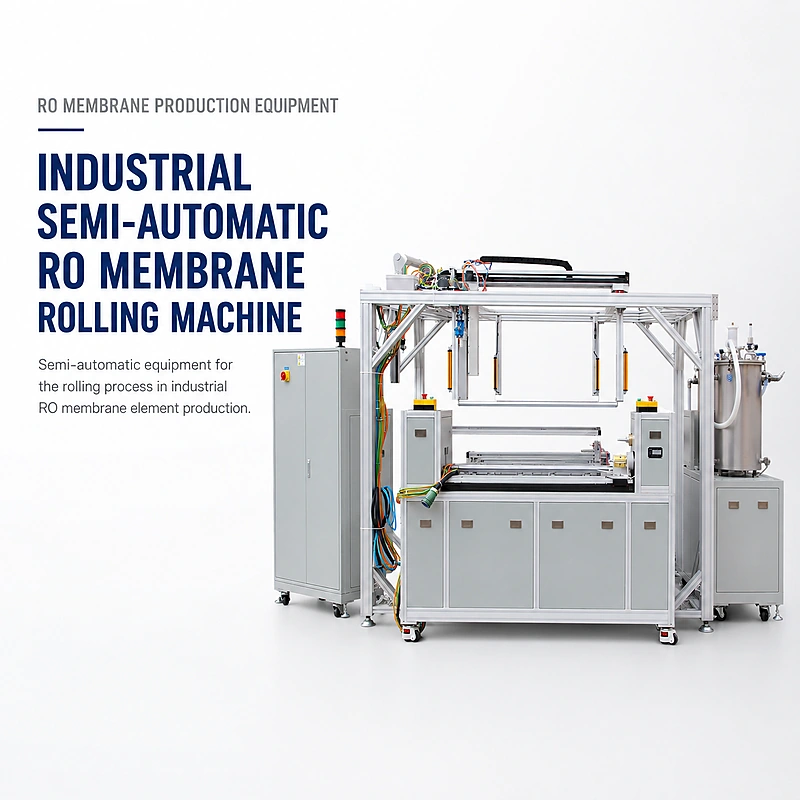
Not without a diagnosed process requirement. If the investigation identifies a repeatability or setup-control issue, use an agreed trial to show that the proposed change addresses it. Ask for measurable acceptance criteria and record the before-and-after results. Avoid accepting “anti-telescoping machine” as a substitute for a validated element design and operating envelope.
For the production record, use the element quality-control checklist to organise inspection and release evidence. A test record should name the method and conditions, not simply say “passed.”
What should you do when telescoping is suspected?
- Preserve the evidence. Retain alarm logs, operating trends and the original element position. Take photographs before moving, trimming or otherwise altering the damaged area.
- Identify the complete assembly. Record element model, serial number, vessel identification, position, orientation and the relevant support parts.
- Separate observation from hypothesis. Record visible layer movement independently from possible explanations such as an operating transient or an assembly mismatch.
- Agree the investigation method. Ask the element supplier or responsible engineer which inspections and tests apply. Do not improvise a pressure test or destructive examination.
- Document disposition and corrective action. Keep the decision about replacement or further examination separate from the action intended to stop recurrence.
Can you push the layers back or add more outer tape?
Neither action demonstrates that internal integrity has been restored. Reworking the visible end can also destroy evidence needed for diagnosis. Do not return a suspect element to service on the basis of its improved appearance. Obtain a documented disposition from the responsible element supplier or engineer.
Will a leak test identify the original cause?
A test result answers a defined test question under defined conditions; it is not the whole failure history. A failed integrity test does not distinguish every possible origin of damage. A passing result is also not, by itself, a clearance to reuse a visibly displaced assembly. Review the result alongside the mechanical findings and operating record.
How can you prevent recurrence without guessing?
Make the corrective action traceable to the evidence. If the cause remains uncertain, state that clearly and agree what additional data are needed. A permanent purchasing or production change should not be justified by an untested theory.
| Evidence points toward | Responsible review | Close-out record |
|---|---|---|
| Operating or startup conditions | System designer and operating team compare the event with approved limits and procedures | Revised procedure or control settings, approval and subsequent operating trend |
| Support or installation mismatch | Element and vessel documentation reviewed against the actual assembly | Correct part identities, installation record and authorised inspection |
| Manufacturing nonconformance | Recipe, material lot and process records compared with the approved build | Corrective-action trial, acceptance results and affected-lot disposition |
| Insufficient evidence | Agree a monitored investigation rather than assigning blame | Data-collection plan, responsible person and review criteria |
What information helps a supplier investigate faster?
A clear incident report is more useful than a message saying “the membrane is bad.” You do not need to know the cause before asking for help. You do need to distinguish measured facts from assumptions.
Copy-ready incident report checklist
- Element manufacturer, model, serial number and installation date.
- System, stage, vessel and element position; marked feed direction.
- Full-element photo, both end views and close-ups with a scale where safe.
- First observation time and the last known normal condition.
- Feed and concentrate pressure, measurement locations, units and corresponding flows.
- Temperature, pretreatment changes, startup events, cleaning and maintenance history.
- Observed performance change and any test method already used.
- Support-part identities and available installation drawings.
- For manufacturers: recipe revision, material lots, assembly and release records.
- Requested help: component fit review, manufacturing review or referral to the responsible system/element supplier.
Need a component or manufacturing review?
WECOME supplies RO element materials, components and production equipment. Share your assembly drawing, part identification and production evidence to discuss the relevant scope. Field operating limits and permission to reuse a damaged element must come from the responsible element or system supplier.
Discuss the Technical ReviewFrequently asked questions
Is telescoping the same as low salt rejection?
No. Telescoping describes mechanical displacement; salt rejection describes separation performance. They may occur together, but a rejection result alone does not identify the mechanical condition.
Does high feed pressure automatically mean telescoping?
No. Feed pressure and feed-to-concentrate differential pressure are different measurements. Record the relevant pressure difference, flow conditions and model-specific limits instead of judging the event from feed pressure alone.
Can an ATD cap compensate for excessive pressure drop?
Do not treat it as permission to exceed the element’s specified limits. Review the complete support arrangement and operating conditions, not just whether a cap is present.
Is there one safe differential-pressure limit for every RO membrane?
No universal value is provided here. Use the documentation for the exact element and system, and distinguish a single-element limit from a vessel or stage measurement.
Is tape-roll telescoping the same failure?
No. Sideways displacement within a supply roll of tape is a different object and inspection problem. This article concerns axial movement of the wound pack inside an RO membrane element.
Technical sources and scope
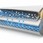
This guide combines manufacturer references with an original incident-recording checklist. It is not a failure certificate, a universal operating specification or a substitute for the applicable element and vessel instructions. The diagrams are simplified explanations, not photographs of customer failures.
- DuPont FilmTec RO/NF Technical Manual: Telescoping, section 8.5.2, pages 164-165, Rev. 20, August 2026. Supports the definition, possible internal damage and support consideration.
- DuPont FilmTec RO/NF Technical Manual: High Pressure Drop, section 8.5.3. Consult the applicable model documentation for limits.
- DuPont FilmTec: Biological Fouling Prevention, Form 45-D01567. Explains the connection between biofouling and rising differential pressure.

Bessie has 10+ years of experience in RO membrane materials and water treatment supply chains. At WECOME, she helps manufacturers and system integrators worldwide source the right membrane components — from feed spacers and permeate carriers to NSF-certified adhesives — backed by hands-on technical support.